
Canadians, rejoice! Not only do you have curling, the Big Turk and Tim Hortons (and, when I was in BC last, Dr Pepper made with real cane sugar), you also have a number of interesting indigenous computers like the underappreciated Micro Computer Machines MCM/70 portable, the Tarot Electronics MIMIC (not to be confused with the more notorious Spartan Mimic), the Dynalogic Hyperion and of course the NABU Personal Computer. And, like your neighbours to the south, you have terminals too, most notably the Telidon and Alextel.
Terminals, however, are in many cases based on general purpose architectures, just lashed to restrictive firmware — a good example would be the DEC VT220 which is controlled by our old friend the Intel 8051 — and game consoles likewise fall naturally in this category. Plus, there’s a third group of computer-adjacent devices that qualify as well: the video titlers.

Video titlers (also known as character generators) are exactly what they sound like: devices that stamp bitmap data, usually text, on top of a video signal, like this typical example from a 1992 demo video for the consumer-oriented Videonics Video Titler. Distinct from what you might do as part of an editing system, many of these machines operate in real-time and over live video input such as the classic Chyron systems. Today’s titlers are usually add-on boards controlled by a standard desktop computer, but for much of their existence they came as standalone devices with their own CPUs and video hardware, and that means they can be potentially hardware-hacked like anything else.
Well, Canada, you have your own indigenous video titlers as well, and here’s one designed and manufactured in beautiful Montréal: the Scriptovision Super Micro Script, circa 1985.

The Super Micro Script was one of several such machines this company made over its lifetime, a stylish self-contained box capable of emitting a 32×16 small or 10×4 large character layer with 64×32 block graphics in eight colours. It could even directly overlay its output over a composite video signal using a built-in genlock, one of the earliest such consumer units to do so. Crack this unit open, however, and you’ll find the show controlled by an off-the-shelf Motorola 6800-family microcontroller and a Motorola 6847 VDG video chip, making it a relative of contemporary 1980s home computers that sometimes used nearly exactly the same architecture.
More important than that, though, it has socketed EPROMs we can theoretically pull and substitute with our own — though we’ll have to figure out why the ROMs look like nonsense, and there’s also the small matter of this unit failing to generate a picture. Nevertheless, when we’re done, another homegrown Canadian computer will rise and shine. We’ll even add a bitbanged serial port and write a MAME emulation driver for it so we can develop software quickly … after we fix it first.

Notwithstanding filmed art and transparencies, early static television titles were generated by monoscopes, modified cathode ray tubes that fired their electron guns at embedded plates marked with a metallized image. These units then assimilated the reflected particles into a sharp monochrome video signal. Related devices like the 1953 Hughes Typotron or 1954 Convair Charactron used a double-deflection system where an electron beam was first used to illuminate selected glyphs in a perforated stencil anode and then onto the desired position on the screen.

The union of the monoscope with these techniques yielded hybrids like the 1966 Raytheon CK1414 and 1969 RCA 4560, which could produce a display character by character by having a monoscope repeatedly scan subsections of a plate “font” under computer control. The resulting signal was then used to generate each display frame on a second CRT. Although crude and sometimes flickery, these methods yielded sharp clean characters that were clearly more flexible than fixed monoscope images or labouriously creating superimposable high-contrast art with stencils and Letraset sheets.

Simultaneously, solid state systems equipped with what we would now call bitmap images, stored in core memory, could string them together on the fly to generate simple fixed-width font displays. In 1970 CBS Laboratories expanded on this technology with the Vidifont, the first video title generator capable of proportional characters. It was sold openly until CBS shuttered the CBS Laboratories division and the Vidifont was further internally refined into a colour-capable version exclusively used for CBS News broadcasts. (CBS later won an Emmy in 1992 for the Vidifont’s development.) Meanwhile, Systems Research Corporation, a contractor who provided the Vidifont’s “Vidiloop” tape storage system used for creating text off-line before running it on-air, spied an opportunity and got into the market themselves. Their first product in 1971, the Chiron [sic], used the competing 1967 AB Dick Videograph 990 with an improved monospace font and colourized text, supporting creation of full-frame and lower-thirds displays that could be recorded and retrieved. The name was later changed to Chyron due to an existing trade name in California, and renaming themselves after their flagship product, the Chyron Corporation became virtually synonymous with broadcast TV graphics. One of SRC’s original founders was Francis Mechner, a research psychologist who had recently sold his company to Xerox and was SRC/Chyron’s initial investor, and whose eldest son Jordan Mechner went on to develop games like Karateka and Prince of Persia.

Such devices generally produced their output using large and complex assemblies made from discrete components, which also made them prohibitively expensive outside of the studio. Although multi-chip assemblies could generate bit patterns using early types of MOS ROM, the first complete character generator “on a chip” wasn’t introduced until 1969, the TMS2400JC series from Texas Instruments. (The earlier Fairchild 3250 character generator could only emit numbers.) Presented with an input — which could come directly from the data bus — these chips would emit a 5×7 character from an internal mask array selectable by row, suitable for conversion to a video signal, with its simultaneous sibling TMS4100JC and TMS4880JC series offering alternative character matrix sizes. This chip family became one of a long series of TI character generators and was used in devices like the Alphacom Terminal Computer, though their output was not sufficiently high quality for general broadcast use. An evolved version of the concept appeared in the 1972 Signetics 2513, best known as the character generator in the original Apple I.
By 1980 a number of relatively inexpensive video display chips were available on the open market, all capable of basic text output and even some simple graphics, including the Signetics 2637 Universal Video Interface (UVI), the Texas Instruments TMS9918 Video Display Processor (VDP) and the Motorola 6847 Video Display Generator (VDG). Videotape recording had also gotten less expensive in the meantime, putting it within reach of a sufficiently determined (or financially irresponsible) enthusiast, and these were certainly the very same people who wanted to do their own character work just like the TV studios. It’s not exactly clear what would qualify as the first home video titler, and many early home computers were likely used for such a task, but one Canadian company in particular surely has a strong claim.

Scriptovision was founded in Montréal, Québec by Michel and Robert Champagne in 1981. Their inagural product was developed that same year and a strong contender to be our landmark first: the Micro Script, a handheld character generator with a blister keypad that could produce 32×16 text simultaneously with simple 64×32 colour block graphics over composite video. I can find no obvious references to a similar prosumer product prior to theirs, so I proffer it as the winner. The Champagnes produced both fully assembled units and kit parts, with a complete ready-to-go unit available for US$169 [in 2026 dollars about $580] “plus 4.7% import duty” if shipped to the United States. Michel Champagne wrote a two-part article for Radio-Electronics in April and May 1982 discussing its internals and its operation, including a full schematic and images of the printed circuit board.

The Micro Script did not have a built-in genlock (short for “generator lock”), which is to say it could not overlay its own output over another video signal, though this also made it less electronically complex and therefore cheaper. Its simple display was nevertheless amenable to being used in that fashion with an external genlock or similar device, such as this still from a YouTube video that employed a slightly later Micro Script Model II. A user could create up to two “pages” of artwork and flip between them instantly, though the device was intended for immediate use as the Micro Script had no facility for saving or reloading its contents.

To a certain class of (Tandy or Dick Smith) user, the font in that grab will have given away exactly what was producing the image: a Motorola 6847 (“MC6847”) Video Display Generator. The Micro Script is very close to Motorola’s reference design, pairing a 6800-family CPU — in this case a Motorola 6802 microcontroller, incorporating an on-chip oscillator and 128 bytes of RAM — with the VDG and two 2114 static RAMs providing the two 512-byte pages of display memory (i.e., 1K). The VDG’s Y-Pb-Pr output lines are then connected to a Motorola 1372 (“MC1372”) video modulator which in this application directly generates the device’s composite output, though the MC1372 can also produce RF for connection to a standard-definition TV. Both the VDG and the MC6802 are driven by a standard 3.58MHz crystal (i.e., 315/88, the NTSC colourburst subcarrier frequency), which the CPU internally divides by four to yield its nominal clock rate of 0.89MHz (315/352).
The VDG is a nearly autonomous chip which generates an image from connected memory independently of the CPU. It does not map anywhere in memory per se and it has no external registers for a CPU to manipulate. Forcing a particular mode such as bitmap graphics requires controlling chip lines, which in machines with software-controllable video modes must be provided by extra hardware. On every screen refresh, the MC6847 reads memory and creates a frame based on its option inputs; since character attributes are also selected by chip lines instead of registers, the data bus lines for certain bits are often wired to these lines so that each character cell can have its own attributes, which the chip will consult as it fetches. Here, this is accomplished by wiring bit 6 to both the VDG’s data bus and to its Alphanumeric/Semigraphics line, and bit 7 to both the data bus and the VDG’s inverse video line. Other mode control lines are hardwired to +5V or ground, limiting this application to the internal character ROM and “semigraphics 4” mode (four blocks per character cell), selectable by cell — interestingly, the 6847’s CSS line, selecting one of two text colour palettes, is instead controlled globally using one of the keypad buttons.
Because the VDG and the CPU must access the same RAM for display, there is an inevitable risk of collision, even with CPUs like the MOS 6502 that are off the bus for much of their machine cycle. Unlike systems like the Tandy Color Computers, the Micro Script has nothing like the 6883 SAM to arbitrate between the CPU and the VDG; the Micro Script’s small 2K ROM instead keeps its working data and processor stack in the CPU’s internal RAM, only using the 2114 SRAMs for storing characters and semigraphics for display. Two 74LS367 tri-state hex buffers and a 74LS245 octal bus transceiver serve as bus arbitrators, protecting the 6802 from the 6847’s bus activity and suppressing the VDG on its MS pin when the CPU accesses the SRAMs (gated via a 74LS138 used for address decoding). Although the MC6847 can generate a signal on its FS pin when it finishes drawing a frame, which in many systems is wired to the CPU’s interrupt line, here the CPU’s halt, IRQ and NMI (and memory ready, incidentally) lines are all hardwired high. Instead, the 6847’s FS line runs to one of the 74LS367s and then to the data bus which the CPU can busy-read as a single bit. The Micro Script’s ROM constantly checks this bit, waiting for the precise time it goes low, after which the CPU is guaranteed 32 scan lines where the VDG will not interfere. This period equals 32 times the NTSC horizontal scan time of (1/(13500/858)) milliseconds (~2.03ms), or approximately 440 cycles at the MC6802’s clock speed. This number will become important later.

The Micro Script is a very simple architecture, but categorical home computers have been built on designs nearly as uncomplicated. The 1979 APF Imagination Machine paired a 6800 with a 6847, both at the same speed as the Micro Script, and a simple one-channel sound generator. The base unit, the 1978 APF MP1000, was a cartridge game console with built-in controllers sold for a similar price to the Micro Script, and designed to compete against the Atari 2600 with 1K of built-in RAM — which the Micro Script also has. Note that this is not sufficient memory for the VDG’s bitmap modes, so to enable better graphics the MP1000 has additional hardware which effectively allows a custom character set to be defined in one 512 byte half and displayed as text from the other. The Imagination Machine accepts the MP1000 and adds a cassette deck, keyboard, more RAM, and expansion options (the unreleased Imagination Machine II consolidated the MP1000 into the chassis).

Or how about the VTech Laser 200, perhaps best known in its Australian rebadge as the Dick Smith VZ200 Personal Colour Computer? One of the cavalcade of super-low-end 1983 home systems, this machine pairs up the VDG with a Zilog Z80 instead, though both still ran at the same 3.58MHz speed (despite the PAL locality for AU/NZ). The base 8K VZ-200/Laser 200 system devoted 2K of its built-in RAM to the VDG, just enough for a 128×64 bitmap mode in four colours and the standard text/semigraphics mode, and also used a 74LS245 to gate CPU access to this specific tract of memory. A cheap and well-supported entry to home computing down under, the VZ200 and the upgraded VZ300 were beloved in their adopted home country and we’ll be looking at these computers in a future article.

Or what about Radio Shack? Tandy, never one to let anyone else define the bottom of the market, had a system like this of their own that was even cloned in France — the TRS-80 MC-10 Micro Color Computer, another low-binned 1983 system that was “new for 1984” in the RSC-10 catalogue. Superficially a stripped-down Color Computer, the MC-10 actually uses a different CPU — the MC6803, more closely related to the 6800 (and 6802) than the CoCo’s 6809, and also at 0.89MHz from a 3.58MHz crystal. There’s no SAM in the MC-10 to arbitrate the bus either, just another 74LS245 controlling access to its 4K of RAM. Although the 6803 has a serial port which the 6802 lacks, the on-board RS-232 is in fact bitbanged because the 3.58MHz crystal cannot be used to generate any standard baud rate with an integer divider. The machine was hobbled by its intentional design limitations and the poor quality (and quantity) of available software, and after reviewers mercilessly savaged it Tandy slashed the price and discontinued it about a year later. Nevertheless, the MC-10 survived briefly in an alternative French form as the cherry-red Matra Alice, another competitor for the French Plan Informatique pour Tous (“computing for all”) school initiative alongside the Exelvision and Thomson systems. Similarly unsuccessful, it nevertheless spawned two direct successors which added more RAM and replaced the MC6847 VDG with a Thomson EF9345, as used in Minitel terminals.
The upshot of all this is that the Micro Script, other than its ROMs, was not that far divorced in either architecture or capability from contemporary home computers and even some later ones. Indeed, that goes just as much for its follow-on, which is our victim of the day.

The Micro Script and Micro Script II sold well enough (certainly as kits, but based on surviving examples more so as fully-assembled units) for the Champagnes to design a successor, though this time as a fully commercial product for prosumers: the 1985 Scriptovision Super Micro Script, introduced at just under $500 [in 2026 dollars about $1500]. Popular Photography in their October 1985 issue called it “the lowest-priced character generator in a separate unit that we have seen.” Sold in a handsome compact custom enclosure with wood trim, it supported the same eight-colour palette and generated two font sizes, with the larger font in any of the eight colours. It also introduced an internal genlock for overlaying output on a connected video signal, a battery backup (with two AAs) for maintaining the contents of RAM, and a separate port for an external RF modulator which could mix the final video output with an audio signal.

It must have been a success for the small company, because in this 1987 advertisement they were still selling it, then reduced to $350 [$980], and advertisements for the product continued to run as late as 1989. Since their previous address appears to now be a private residence, I have censored it from this image. A demonstration videotape was available for $10, though I have yet to see it, and it appears no one has digitized it. The Super Micro Script was sold openly, both direct from Scriptovision and through various distributors.

While I surmise the Videonics Video TitleMaker family was the best cumulatively selling titler in this class, a conclusion purely based on the number still offered for sale on eBay, the Super Micro Script seems to have sold widely enough to be at least as common today as its ancestor the Micro Script and perhaps even more so. I spotted one a couple months back for cheap because the seller said it wasn’t working, and I figured it might make a nice little project enclosure if I couldn’t fix it: it has a 5×8 (40 key) keypad which was a bit grimy, a slide fader for controlling the opacity of the generated text overlay, multiple RCA jacks, and power and genlock switches. It came with its wallwart power adapter but no manual or other paraphernalia. Later I found a second example while I was doing the write-up which was fully operational, though it was sold untested since it didn’t even come with the wallwart.
At the time it arrived, I had no knowledge of the device’s architecture or function other than it was an early character generator, and I had yet to find Michel Champagne’s complete technical description of its ancestor until I started on the historical research for this article. I’ll throw in some “notes from the future” as we go through it, but I’ll write this teardown of the Super Micro Script — which I’ll abbreviate periodically as the SMS — mostly as I had previously performed it unaided at the time, and it has some unique attributes of its own that we’ll have to unravel ourselves anyway.

On the rear are its ports. New on the SMS is a 5-pin DIN port for connecting an external RF modulator, the pinout of which we’ll determine shortly. (Keeping the RF modulator external might have also helped them avoid explicitly having to obtain FCC Part 15 certification, which in those days was notoriously strict; see also the Apple II Sup’R’Mod.) However, its native output is still composite, which it provides on both a preview output — the only output the Micro Script provided — and a fully mixed output incorporating the genlock. Video input, audio input and the external power connector complete the set. The serial number is #268910; my second unit is serial #270209.

The main assembly is within a sturdy steel sheet-metal case, which surely did well for reducing interference both to and from the unit. I could also hear something rattling inside as I moved it around, so let’s get it open. It is released from its moorings on the bottom by unscrewing the feet and lifting the top of the unit off.

You can then flip back the top portion with the controls, to which the mainboard is bolted, and then lift the whole thing off the base plate. Immediately the rattling was revealed: the old, old alkaline batteries had come out from their holder. (On my second unit, the batteries had leaked and actually corroded off their own negative lead!) Fortunately, due to the way the mainboard is mounted, they would not have been easily able to leak onto the electronics as long as the unit remained right way up — which is more than I can say for some Apple systems I’ve encountered.

The mainboard PCB is double-sided but only one side has components, so we will concentrate on the other side for the rest of this entry.

The Super Micro Script mainboard is about half again as large as the Micro Script’s. Although the metal on the PCB carries the legend “SMS 6000 iss[ue] 1A,” most of the markings on the board are silkscreened on, including “MICRO SCRIPT” in the lower right corner — but despite this appellation and being evolved from the earlier design, the board bears little resemblance to the original Micro Script PCB even though their IC designations largely match. While the board itself was clearly mass-produced, the hand-numbered UV EPROMs (both apparently 4K D2732As or equivalent) and the appearance of the solderwork suggest final assembly was done manually. (Proudly manufactured in Canada!) This unit must also have been relatively early given the 1983 and 1984 production dates on most of its chips. The 3.579545MHz crystal is the shiny “can” under the EPROM marked “2.”
Later Scriptovision started using a green consolidated board. This is the one in my second unit and is marked “SMS 6000 iss[ue] 3.” We’ll come back to this board when we start talking about the Super Micro Script’s various obfuscations. I don’t know how many board versions there ultimately were.

The CPU is marked AMI S68B02P, a 68B02 in a plastic DIP manufactured by American Microsystems as a second source. The 68B02 is rated to 2.0MHz and substitutes directly for the 68A02 (top clock speed 1.5MHz) and original MC6802 (1.0MHz). Its primary advantage over the original 6800, besides its 128 bytes of on-chip RAM, is an integrated internal oscillator that generates both clock phases from a single source instead of the two inputs required by the 6800. What is almost certainly the main program ROM is next to it, a 4K NEC D2732A marked with the number “1.” A small set of jumpers next to it go both to the ROM and to the 74LS138, which suggests they are involved with where it maps in memory, so I left them alone. We’ll come back to the 74LS273 and 74LS244 chips above the CPU in this picture when we get to adding a serial receive port; these chips handle much of the system’s memory-mapped I/O, including the keyboard lines.

On a small daughtercard on the other side of the board sits the VDG, here an MC6847P in a plastic DIP also. The daughtercard is for providing the VDG an external font ROM (marked “2”), a higher quality font than the default one built into the 6847, assisted by the 74LS161 to generate each character’s row addresses. This ROM is expected to carry some reasonable number of 8×12 glyphs (stored as 8×16), though the presence of the D2732A main ROM suggested this one was probably one too and therefore would have 256 glyphs to equal 4Kbytes. (We’ll confirm later that this is in fact the case.) The daughtercard looks like a factory upgrade, with the VDG’s pinout appearing to match the socket it is installed in, but the daughtercard is in there very tight and I didn’t want to damage it with a hasty extraction. Also, although the wiring indicates the board could either accept a VDG by itself or a VDG on the font ROM daughtercard, only this unit has a daughtercard — the later issue 3 device consolidates it into the logic board. The Micro Script and Micro Script II don’t seem to have supported an external font ROM, so this was new for the Super Micro Script.
On the mainboard under the daughtercard we also see the same Motorola MC1372 we saw in the Micro Script, which I already knew was undoubtedly generating the composite output, and was high on my list of suspects if the seller was right about its inability to emit a picture.

Also under the daughtercard are the two 74LS367s we saw in the Micro Script, though at this point I didn’t know their exact purpose. However, next to those are what looked like two SRAM chips piggybacked on each other in a most unusual fashion which also appear to be hand-soldered. I couldn’t get a light probe on its top to see what it was, but later we’ll find out this machine has 4K of RAM and thus these would likely be 2116 or 6116 SRAMs. No other RAMs are visible on the board, so apart from the 6802’s internal RAM this dagwood RAM sandwich is all it’s got. How we actually deal with its atypical RAM configuration will become a major topic in the second half of this article.

Up near the back are the various wires going to the rear ports. The board appears to accept a single +9V DC input, plus ground, video in, video out and +3V from the battery compartment. Although the 6802 has a standby feature that preserves part of its internal RAM with low power from one of its pins, this wouldn’t be enough to power the RAM sandwich, so the AA batteries preserve the entire contents of the external RAM instead of the 6802’s standby RAM.

The rear jacks are here. Notice there are few explicit grounds: instead, the ground portion of the power input and most of the RCA jacks is simply soldered to the sheet metal, the portions around them having the enamel paint scratched off, making the entire case one big common ground. Another set of ground wires goes from the RF modulator to the negative pole of the battery compartment and from the sleeve of the video input. This last one is bolted onto the metal top of a 7805 voltage regulator which is also secured to the sheet metal, making the case an oversized heatsink at the same time.
With this view we can now derive the pinout for the RF modulator. If we orient the notch to the top (i.e., have the unit upside down) while we look at the female rear port, numbering the pins from left to right, pin one is audio, pins two and three are tied together to ground, pin four is video and pin five is +9V from the logic board. Except for the voltage, this would match things like a Commodore VIC-20 RF modulator (+6V) or the TI 99/4A’s (+12V).

The wallwart that came with the unit is nominally 9V, tip positive (1/8″ TRS). However, it’s an old unregulated thing and the multimeter read +12V off it, though the voltage might get pulled down to +9V depending on how much current the device draws, so I decided to put it on a bench supply first. Fortunately the power input terminals are easy to access.

At +9V it powers on and pulls about half an amp, which would easily reduce the +12V unregulated output into the rated range. I concluded the wallwart was probably fine.

But the screen wasn’t. Now, I have no manual for this, so I had no idea precisely what I was expecting to see, but no amount of adjustment on our trusty Commodore 1702 monitor would generate a stable picture even though I could see what looked like letters. Eyeballing it, it looked like the horizontal sync was totally shot, and both the preview out and video out jacks generated the same distorted image. On the other hand, the fact I could see recognizable, sensible text strongly suggested the CPU and probably the VDG were both okay.

Interestingly, if I messed with the genlock switch enough, I could glitch it into a much better picture — colours were probably wrong and it still flickered, but this gave me hope that possibly even the MC1372 was fine and the real problem lay in the output stage from there, perhaps a bad cap or something.

The main menu also responded to me pressing 4 on the keypad to display the colour palette, though this didn’t match at all what I would expect from a 6847 nor the example palette painted on the SMS case. But it’s alive! We have a pulse and it’s talking to us!
There was still an outside chance that the MC1372 was bad, but it so happens that for any system with a 6847/1372 combo there’s an easy way of finding out, and it can even be installed without altering the logic board: put in a Color Computer composite modification, like the Mark Data Universal Video Driver or one of its modern clones. Now, wait, I hear you say, doesn’t the Super Micro Script have composite output already? It does indeed, but the idea is that if the problem is in one of the downstream components between the MC1372 and the video out port, then the comp mod will act as a bypass and generate a proper image on its own output. On the other hand, if the MC1372 or the VDG are at fault, then the picture from the composite mod board will also be bad. Either way we’ll be better able to narrow down what broke.

The theory of hooking up the comp mod (this particular one was an eBay purchase; I am not affiliated with this seller or any other) would be the same as for a regular CoCo; we just have to find equivalent points for it on the SMS. The black clip for audio can be immediately dispensed with since this board does not generate sound and the “silver” one for ground (though this clip is more like blue) can go right on one of the copper ground wires. The other clips will need proper board points, though the clips used here are kind of big for getting around the SMS’ chip legs, so I buzzed out pin connections for discrete components I could better attach to instead. The red clip for +5V went on the edge side of the R12 resistor where I found a nice strong voltage reading, and the green clip for the MC1372’s chroma output, from the chip’s pin 7, went on the ports-side of R15.
On the other hand, I didn’t find a component I could attach the yellow clip to for the luma output from the 6847 and I could not get the yellow clip easily around its leg. For the purposes of testing, I got one of my smaller test clips and put that on, and clipped the yellow clip from the comp mod to its wire. I then plugged the 1702 into the output from the comp mod, and …

… we have a good image!

I got out the USB composite capture device and indeed we have beautiful output from the composite board. (The screen grabs in this article have been corrected and cropped to the proper 4:3 aspect ratio but are otherwise unretouched.)
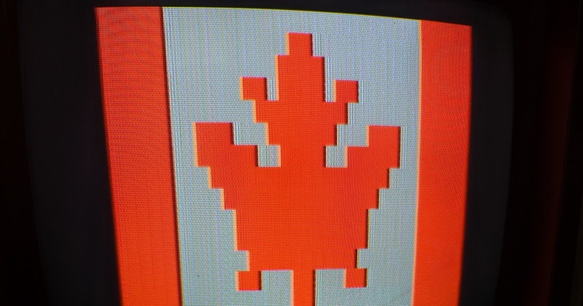
While the VDG offers two text colour palettes, green on dark green and orange on dark orange, most computers based on the MC6847 (like the Tandy Color Computers, Samsung SPC-1000, Dragon 32/64, etc.) use the first one. The SMS, on the other hand, exclusively uses the orange palette. This choice is controlled with the CSS pin which the majority of such sysytems — though not the original Micro Script, which made this choice selectable, nor the APF or NEC TREK — hardwire to a unchangeable fixed logic level. As semigraphics and text can coexist in this screen mode, the SMS ROM then uses an all-black rugby team semigraphics character to extinguish the background around the text, which is why the entire screen isn’t dark orange.

Solid semigraphics characters are also used to generate the colour bars display (when pressing the “4” key from the main menu). This is the most colourful mode the VDG can generate and the only mode supported on the SMS. In order, the eight colours are green (same green as the text mode green), yellow, blue, red, “buff” (a very light grey), cyan, purple and orange (same orange as the text mode orange). These colours can be accompanied by black in any semigraphics character, while the darker text background colour, whatever it happens to be, can serve as a phantom tenth colour. The colours are quite vibrant and even on my fully working SMS without the comp mod seem more saturated than my CoCo 3.
Now, with this board bypassing everything between the MC1372 and the rear ports, what about the genlock? If I flick on the genlock, the picture — from the comp mod, remember, not from the rear jacks — disappears. After some puzzlement, I realized this could only happen if the genlock switch turns out to change the path of the video signal on the board.

For yuks, I dug out my Emerson VHS deck — yes, for the first time in an Old VCR article, but probably not the last, we’re going to use an actual old VCR. This generates a nice clean composite signal of its own as shown on the 1702. I plugged it into the SMS’ video input jack and hit the genlock switch once more.

Now we actually have a screen again — though remember that this display is coming from the comp mod, not the rear jacks. It’s somewhat warped and the character colours have become more desaturated, but we have sync between the VCR and the SMS, and that sync seems to be getting picked up by the mod. Although this implies some portion of the genlock is working, we’ll come back to this presently.
Meanwhile, since we’re getting really nice low-noise frame captures, let’s have a look around. Again, I have no manual for this, so everything I’ll demonstrate here was discovered by simple trial and error.
The Micro Script had no main menu, but the SMS does, which pops up immediately on power on. Although seven screens are officially available, this menu itself must surely count as a screen too, so eight times 512 equals our 4096 bytes of RAM. From here you can start a slideshow (“page cycling”) or a bottom-line crawl, though these modes are generated from the same set of screens. The speed and content range are all selectable with the number keys, using the up and down arrows to change the value.

The asterisk key on the keypad toggles between the main menu and the screen editor. The screens are not cleared when you turn on the machine — because if you have functional batteries installed, you’ll just go right back into whatever screens you were designing earlier.
At the bottom of the screen a little mode line periodically flashes. This tells you, in order, whether you are entering text or semigraphic characters, whether the cursor moves horizontally or vertically, and which of the seven pages is being displayed.

To clear the screen, hold down the CLEAR key on the keypad; this will clear the screen to black characters, leaving just the blue cursor and the mode line. This only affects the current page, so to clear other pages you must switch to them first. You could do so by starting a slide show and hitting asterisk when you get to the one you want, or you could also just go directly to a page by number by pressing the PAGE key on the keypad and then the page number (1-7).

Regular text is entered by simply typing it on the keypad. There is no lowercase with the default font ROM, so the SHIFT key handles things like punctuation symbols and even numbers. Text only appears in the basic orange-on-not-so-bright-orange colour scheme, even if the COLOR key is pressed; there is no “inverse” capability even though the VDG is perfectly capable of displaying it. Notably, the ERASE key doesn’t place a space on screen (if it did, it would be dark orange): instead, it uses the semigraphics 4 character that is entirely black.

By pressing the ZOOM key, enlarged 3×4 characters can be generated. These may appear in multiple colours selected by the COLOR key because they are in fact semigraphics 4 as well. Since 32 is not evenly divisible by three, characters on the far edge will wrap.

The cursor is yuuuge in this mode, but the cursor and the flashing status line may be temporarily quelled with the CURSOR ON OFF key.

It is also possible to manually select and place semigraphic characters directly with CHAR/GRAPHIC. When in this mode, ZOOM cycles through the available characters and COLOR through the available colours.

The ability to generate a slide show by placing content on multiple screens should be obvious, and the ROM supports this, but it’s less obvious how this works with the bottom crawl mode. We’ll put some more big text here to show you how that looks since it can crawl both regular and zoomed characters.

Interestingly, while the slide show has no problem with all seven available screens, you may not use the seventh one in crawl mode, probably for buffering purposes. (The menu occupies the remaining eighth screen.)

We’ll retract it to screen six and then start the scroll. Scroll speed is also adjustable using the delay setting, the same one used for the delay between screens, which can be from one (fastest) to thirty (slowest).

The scroll routine runs text from the top of each screen, left to right, top to bottom.

It is also smart enough to know the difference between regular and zoomed characters: if it detects what it thinks are semigraphics, it will take it as a four-row block.

This mostly works for other kinds of graphics, even if the art doesn’t exactly match those dimensions.

The scroll continues through all the screens you specify, even if they contain junk (in that case they undoubtedly have semicharacters in them and get taken as four-row blocks too). We’ll stop it here.

It is possible to lay down vertical strips of characters with HOR./VERT., but these don’t rotate the actual glyphs, of course.

This is less useful in the scroll mode because how many characters of a vertical strip end up in the scroll depends on whether the routine sees semigraphics there or not:


… but it’s still handy for certain types of slide displays.
The next two orders of business would be to dump the ROMs for posterity and hopefully study, and then to see what we could do with the genlock.

Being vanilla 2732A EPROMs, the two internal ROM chips can be read in pretty much anything, and I got good reliable dumps of both. Since we’re most interested in the main code, we’ll now rig up a ROM emulator so that we can modify it.

I am not affiliated with My Geeky Hobby, but he makes a very nice Arduino-based open-source ROM emulator kit. This can take a binary (for testing purposes, our dump) and present it in multiple configurations as if it were an actual ROM. It includes a probe that replaces the ROM itself.

To get the probe to clear the nearby wires and components without contacting them, I put a strip of electrical tape over the exposed sections and then mounted the probe in another socket to give it a little extra height. Since the 2732A is only 24 pins, the remaining four (the probe is 28-pin) dangle. The emulator runs fine this way except it can’t draw +5V from the board, meaning it must always be connected to USB power (which for our purposes is no problem).

Starting the system up with no ROM image loaded intentionally to make sure there were no shorts. The CPU is just reading open bus and the RAM is full of garbage, but we have a picture, so we probably didn’t kill anything.

Loading our ROM 1 dump into the emulator and resetting the SMS, we get the menu, so we are now in fully working order. Next, let’s see if we can get the genlock running.


I took two snapshots from my crappy handheld oscilloscope of the output from the internal preview out (top) and the composite bypass (below). The bottom signal from the bypass shows a decent NTSC composite waveform: the sync tip (drop), followed by the colourburst, the black level (flat), and then the horizontal lines. By contrast, the internal video isn’t generating anything recognizeable as vertical sync and the horizontal lines seem to have abnormally small amplitude.

For all that, though, when we connect the monitor to the genlocked output using our VCR again as the composite signal, we do get a picture. It’s distorted and not fully stable, but it’s legible. Interestingly, it is also entirely monochrome — the colour is not in fact overlaid, suggesting this is entirely being generated solely by the luminance output from the VDG and not the chroma information. The MC6847 emits these signals on separate pins. This also means that the output of the VDG used for the genlock is likely a completely parallel pathway from the preview output and we’ll need to deal with them separately.
I have no schematics for this board and while it is certainly derived from the Micro Script, the Super Micro Script has of course moved some components around, some are difficult to access because of the font daughterboard, and obviously I have no documentation of the genlock side. I did some work figuring out where signal paths went and left some notes to myself on the PCB. However, it was straightforward to determine the composite signal from the MC1372 is eventually funneled into a large capacitor at the top before it feeds the preview output.

Since we know the bypass generates a nice picture, I decided to simply use it for the preview output (and, when the genlock is off, the main video output) instead of potentially making a mess by attempting to repair the board directly. I also didn’t want to make any irreversible modifications either, but the capacitor has nice long leads and makes a good point to splice in the output from the bypass, so I clipped the input side to isolate it since even a dolt like me could solder that much back together if needed.

There isn’t much length on the bypass output to wire that directly to the preview output, so I chopped up a cable with enough length.

Next, I got out the soldering iron, soldered the other end of the cable from the bypass to the preview jack, and also cleaned up the wiring from the luminance pin so we didn’t need the “double clip” anymore. However, there is nothing here that can’t be easily undone either.

To ensure this can all fit back into the enclosure, I moved the bypass inside of the metal exterior under the jacks and looped the internal cable back around to the top.

The signal got a bit noisier after that. The internal cable admittedly ended up being longer than it needed to be (which can make it into a big antenna), and there might also be some additional RF interference from the board components since the bypass is now jammed inside an effective Faraday cage with them.

Here’s a comparison grab from the issue 3 unit which we’ll use as an example of the machine’s intended quality. There’s still a bit of fringing, although the issue 3 board is more consolidated, so it may well have better components (I’ll show you a picture of the internals a little later). But I’d say for now our repair is good enough and everything fits within the box.

Doing some more buzzing out of interconnections, the genlock path turns out to run through several adjustment points. The most important two seemed to be R27, a largish variable resistor which controlled the strength of the VDG luminance signal (distinct from the fader slide), and C15, a variable capacitor. I’m not sure what that one exactly does to the signal but tweaking it did stabilize the picture at the expense of compressing the VDG output a bit horizontally. (Later I compared this with the working issue 3 and found that its genlock overlay also doesn’t quite match the geometry of the preview output, so perhaps this is something about the circuitry.)

Nevertheless, with these adjusted, you can compare the width of the display to the non-genlocked version above.

To avoid any takedown notices by using actual movie grabs in this blog — except for the absolutely necessary SCTV joke earlier, rest in peace, Catherine O’Hara — I pulled out one of our family home VHS movies from when we went to Universal Studios Hollywood in 1990 and stuck that in the VCR. Here the fader slide is all the way down, so you just see the video. This was the Animal Actors’ Stage live show which closed in 2023.

And here it is with the fader back up. There’s no shadowing or emphasis around the letters, unfortunately, so they can get blown out in bright portions of the picture.

Here is your humble author attempting to shake hands with Frankenstein. He won.


And here are the colour bars as they appear with genlock on and off. Our blue and red strips have a bit of artifact colouration in the genlock view, though this may be because of the horizontal compression. I think this is as good as we can get at repairing it without a schematic to make additional guesses.
Back to the firmware. Since we have a known good dump of the ROM, let’s try to hack it — and that’s where the real fun starts. Here are the last 128 bytes of it.
00000f80  52 9f e1 cf 81 bb 7e 72  61 08 7b 82 a4 01 cf ff  |R.....~ra.{.....|
00000f90  c9 61 84 04 9c 60 49 32  49 1f ff 01 de e9 d1 c0  |.a...`I2I.......|
00000fa0  90 5a 46 ff 9c 64 00 32  e1 71 71 04 39 f8 b1 2c  |.ZF..d.2.qq.9..,|
00000fb0  64 28 b1 2a 7e e1 e7 82  08 d4 cf a2 9f c0 52 ff  |d(.*~.........R.|
00000fc0  76 76 6c ff 55 1f 65 81  a0 7e 8c 82 00 84 10 ff  |vvl.U.e..~......|
00000fd0  ec 5f 84 01 99 64 18 01  b3 10 bd a2 00 f1 01 b0  |._...d..........|
00000fe0  61 18 84 ff cf 11 c3 08  99 00 7b c2 84 f0 40 3e  |a.........{...@>|
00000ff0  76 98 ee 04 bd a8 64 4a  08 10 a4 59 42 bd 1f 0e  |v.....dJ...YB...|
This is very odd. The reset vector at $fffe-f appears to be $1f0e (the 6800 is big-endian), which is plausible, because it’s possible the ROM could be mapped at multiple locations. However, the other vectors for IRQ, software interrupts and NMIs are bogus. Plus, when we try disassembling the putative reset routine from offset $0f0e (following the assumption the ROM is also visible at $1000), we get gibberish:
% ../f9dasm/f9dasm -6802 -offset 1000 sms1.bin
[...]
Z1F0E   ADCB    $FF,X                    ;1F0E: E9 FF          '..'
        LDX     $FE,X                    ;1F10: EE FE          '..'
        CLRB                             ;1F12: 5F             '_'
        NOP                              ;1F13: 01             '.'
        CMPB    M0009                    ;1F14: D1 09          '..'
        NEGB                             ;1F16: 50             'P'
        NOP                              ;1F17: 01             '.'
        ROL     $01,X                    ;1F18: 69 01          'i.'
        BLE     Z1F20                    ;1F1A: 2F 04          '/.'
        SUBB    M00BF                    ;1F1C: D0 BF          '..'
        CPX     M00A7                    ;1F1E: 9C A7          '..'
Z1F20   NOP                              ;1F20: 01             '.'
        JSR     Z80FF                    ;1F21: BD 80 FF       '...'
        NEGA                             ;1F24: 40             '@'
        JSR     ZCF22                    ;1F25: BD CF 22       '.."'
        FCB     $7B                      ;1F28: 7B             '{'
        CLV                              ;1F29: 0A             '.'
        CMPA    M01BD                    ;1F2A: B1 01 BD       '...'
There is no way this would do anything useful because the X register and stack pointer haven’t been initialized to a predictable value before they’re used. Plus, we end up executing an undefined opcode ($7b) right in our code path, which likely is treated the same as DEC, but makes no sense with the bytes after it. Most of the ROM is in fact this same sort of gibberish; nothing looks clearly executable. Also, we don’t see any strings corresponding to the menu text in any obvious encoding. For example, we would reasonably expect to find a byte sequence like $13, $05, $14 plus some offset (e.g., $53, 45, $54) to match “SET” somewhere, but we don’t. Yet the dump must be good, because the ROM verifies and works when we run it through the ROM emulator.

Arcade game hackers have already guessed: the ROM must be encrypted somehow. Indeed, it looks like Scriptovision themselves were quite concerned about knockoffs; the later issue 3 board in my second Super Micro Script has all the chip markings blotted out (quite a few arcade boards did this too, as it happens), and our adjustment points have also been potted with some sort of glue to discourage any mucking around. If you didn’t know what chips were there — and didn’t have access to back issues of Radio-Electronics to try to match the silkscreened IC numbers — you’d have very few clues to guess at what the ROMs should contain. There would have been a good chance if I’d ended up first with this later unit that you’d be reading a droll and shorter article about the new enclosure I made out of a video titler instead.
Still, this is 1985, where things like public key cryptography in hardware of this sort would be unheard of, and there are no chips visible on either board that would plausibly store an encryption key for something like XOR. There is only this ROM and the font ROM. Otherwise, all the visible logic and ICs are off-the-shelf.
So, if it’s not a chip on the board that does the decryption, what about the board itself doing the decryption? The most obvious technique would be to scramble the address and/or data lines between the ROM and the CPU, and this method was not uncommon either in devices of the era: for example, several Commodore 64 cartridges do this, as do certain cartridges for the Neo Geo. This doesn’t prevent someone from doing a bitwise copy of the ROM(s), which is what we did, but it does prevent using them in another board where the address and data lines aren’t swizzled around in the same way.

Lo and behold, the same thing has occurred here. I did some checks with my continuity tester, theorizing that since the CPU and the main ROM are next to each other they would be directly connected to each other without any intervening components, and indeed they are — but not on the pins I was expecting. Using a silver Sharpie to mark my findings, both the address and data bus lines between ROM 1 and the CPU are swizzled in multiple places (only the lowest 12 address pins need be checked, though, since the ROM is only 4K). I wrote a simple-minded Perl script to unscramble the binary bitwise and looked at the output. The most immediately interesting part is the last 192 bytes.
00000e40  0b 53 45 54 2d 55 50 20  50 41 47 45 17 31 80 80  |.SET-UP PAGE.1..|
00000e50  80 80 43 48 41 4e 47 45  20 44 45 4c 41 59 20 20  |..CHANGE DELAY  |
00000e60  20 20 20 20 17 32 80 80  80 80 53 45 4c 45 43 54  |    .2....SELECT|
00000e70  20 46 49 52 53 54 20 50  41 47 45 20 17 33 80 80  | FIRST PAGE .3..|
00000e80  80 80 53 45 4c 45 43 54  20 4c 41 53 54 20 50 41  |..SELECT LAST PA|
00000e90  47 45 20 20 17 34 80 80  80 80 44 49 53 50 4c 41  |GE  .4....DISPLA|
00000ea0  59 20 43 4f 4c 4f 52 20  42 41 52 20 17 35 80 80  |Y COLOR BAR .5..|
00000eb0  80 80 53 54 41 52 54 20  50 41 47 45 20 43 59 43  |..START PAGE CYC|
00000ec0  4c 49 4e 47 17 36 80 80  80 80 53 54 41 52 54 20  |LING.6....START |
00000ed0  43 52 41 57 4c 20 20 20  20 20 20 20 05 50 52 45  |CRAWL       .PRE|
00000ee0  53 53 02 54 4f 0e 46 49  52 53 54 20 50 41 47 45  |SS.TO.FIRST PAGE|
00000ef0  3a 80 80 80 0e 4c 41 53  54 20 20 50 41 47 45 3a  |:....LAST  PAGE:|
00000f00  80 80 80 09 44 45 4c 41  59 3a 80 80 80 12 49 4e  |....DELAY:....IN|
00000f10  56 41 4c 49 44 20 53 45  4c 45 43 54 49 4f 4e 21  |VALID SELECTION!|
00000f20  1e 49 4e 56 41 4c 49 44  20 46 49 52 53 54 2f 4c  |.INVALID FIRST/L|
00000f30  41 53 54 20 50 41 47 45  20 4e 55 4d 42 45 52 10  |AST PAGE NUMBER.|
00000f40  4e 4f 20 44 41 54 41 20  54 4f 20 43 52 41 57 4c  |NO DATA TO CRAWL|
00000f50  15 55 53 45 20 55 50 20  4f 52 20 44 4f 57 4e 20  |.USE UP OR DOWN |
00000f60  41 52 52 4f 57 53 1f 50  41 47 45 20 37 20 43 41  |ARROWS.PAGE 7 CA|
00000f70  4e 4e 4f 54 20 42 45 20  55 53 45 44 20 46 4f 52  |NNOT BE USED FOR|
00000f80  20 43 52 41 57 4c ff ff  ff ff ff ff ff ff ff ff  | CRAWL..........|
00000f90  ff ff ff ff ff ff ff ff  ff ff ff ff ff ff ff ff  |................|
00000fa0  02 04 fe 4c 02 05 fe 64  02 06 fe 7c 02 08 fe 94  |...L...d...|....|
00000fb0  02 09 fe ac 02 0a fe c4  0a 00 fe 40 00 02 fe dc  |...........@....|
00000fc0  0d 02 fe e2 04 0c fe e5  04 0d fe f4 14 0c ff 03  |................|
00000fd0  ff 1b 0c 00 02 10 0c 00  00 10 0d 00 01 ff ff 0d  |................|
00000fe0  ff 20 ff 3f ff 50 ff 66  ff ff ff ff ff ff ff ff  |. .?.P.f........|
00000ff0  ff ff ff ff ff ff ff ff  ff ff f9 99 ff ff f1 d0  |................|
We see our menu strings, so we must have descrambled it correctly.
Why would Scriptovision do this? My guess is because it’s all off-the-shelf components, this prevents a competitor from using their ROM code in anything but another Super Micro Script unit or exact clone. It doesn’t prevent reading the ROM but it does make it more difficult to modify or rip it off completely, and though I don’t claim to be an expert in copyright law (let alone Canadian copyright law), it might also provide them with a plausible case of infringement if a competitor, failing to grok the scrambling mechanism, nevertheless manufactured a functional copy of the unit with the same ROM in it because the ROM can be copyrighted.
Anyway, now that we understand the process, I created a scrambler that reverses the process, ran the scrambler on the unscrambled binary, confirmed the hashes matched, and sent the re-scrambled version to the ROM emulator. The SMS worked just the same as it did before, so the machine is now fully pwned. We can write arbitrary code, scramble it and have the SMS run it. Yee haw.
With that solved, let’s analyze the code further to see what we can make the hardware do. The reset vector points to $f1d0 and the software interrupt vector to $f999. The other IRQ and NMI vectors are nonsense, so we assume that like the Micro Script there are also no IRQs or NMIs in this system. Disassembling from $f1d0, the reset code is now much more sensible. It starts off like this:
hdlr_RST LDS     #M007F                   ;F1D0: 8E 00 7F       '...'
        CLR     >M000F                   ;F1D3: 7F 00 0F       '...'
        JSR     ZF4F0                    ;F1D6: BD F4 F0       '...'
        LDAB    M0005                    ;F1D9: D6 05          '..'
        CMPB    #$00                     ;F1DB: C1 00          '..'
        BNE     ZF1F0                    ;F1DD: 26 11          '&.'
        LDAB    M0008                    ;F1DF: D6 08          '..'
        CMPB    #$00                     ;F1E1: C1 00          '..'
        BNE     ZF1FE                    ;F1E3: 26 19          '&.'
        LDAB    #$02                     ;F1E5: C6 02          '..'
        STAB    M003F                    ;F1E7: D7 3F          '.?'
        LDAB    M0004                    ;F1E9: D6 04          '..'
        JSR     ZF429                    ;F1EB: BD F4 29       '..)'
        BRA     ZF20A                    ;F1EE: 20 1A          ' .'
[...]
It sets the stack pointer to $007f, which is at the end of the 6802’s built-in RAM, and then proceeds to do some opaque calls and tests we don’t understand at the moment. We’ll come back to this.
As a proof of concept and basic primitive we should first figure out how to write to the display. The VDG uses its own private access to RAM to draw the screen, but this says nothing about where that RAM is mapped in the CPU‘s memory map, and the reset routine at $f1d0 is not immediately informative because we don’t know what most of it does yet. However, we do know where in ROM our menu strings are, and that gives us a critical clue: the only place our set-up page string at $fe40, assuming the first byte is a length byte, is referenced is at $ffba (the 6800 is big-endian). This pointer is surrounded by what is obviously data, not 6800 assembly, but we can guess from the position of SET-UP PAGE on the screen that the two bytes before it are the X,Y coordinate. If so, then it must be part of that larger block of multiple such “records” starting at $ffa0 and bordered on both ends by $ff bytes. This block would be undoubtedly referenced somewhere by the X register, so we should look for where X gets explicitly set to that value, and we find it occurs in two places.
% grep LDX disas.txt | grep FFA0
ZFCCE   LDX     #ZFFA0                   ;FCCE: CE FF A0       '...'
        LDX     #ZFFA0                   ;FDA8: CE FF A0       '...'
Let’s try $fcce first, given that the disassembler assigned it a label because other routines call it.
ZFCCE   LDX     #ZFFA0                   ;FCCE: CE FF A0       '...'
ZFCD1   LDAB    ,X                       ;FCD1: E6 00          '..'
        CMPB    #$FF                     ;FCD3: C1 FF          '..'
        BEQ     ZFCE8                    ;FCD5: 27 11          ''.'
        INX                              ;FCD7: 08             '.'
        LDAA    ,X                       ;FCD8: A6 00          '..'
        INX                              ;FCDA: 08             '.'
        STX     M0016                    ;FCDB: DF 16          '..'
        LDX     ,X                       ;FCDD: EE 00          '..'
        JSR     ZFCE9                    ;FCDF: BD FC E9       '...'
        LDX     M0016                    ;FCE2: DE 16          '..'
        INX                              ;FCE4: 08             '.'
        INX                              ;FCE5: 08             '.'
        BRA     ZFCD1                    ;FCE6: 20 E9          ' .'
This section of code iterates over each of the “records.” On each runthrough it loads the first byte (the X coordinate) into B, stopping if it’s $ff, then the next byte (the Y coordinate) to A, then stashes the current value of X (in $0016) and loads its new value (the string pointer) from the following word. It then calls this routine at $fce9.
ZFCE9   STAB    M003B                    ;FCE9: D7 3B          '.;'
        JSR     ZF38B                    ;FCEB: BD F3 8B       '...'
        JSR     ZF399                    ;FCEE: BD F3 99       '...'
        LDAB    ,X                       ;FCF1: E6 00          '..'
        INX                              ;FCF3: 08             '.'
        JSR     ZF8C7                    ;FCF4: BD F8 C7       '...'
ZFCF7   CMPB    #$00                     ;FCF7: C1 00          '..'
        BMI     ZFD14                    ;FCF9: 2B 19          '+.'
        BEQ     ZFD14                    ;FCFB: 27 17          ''.'
        LDAA    ,X                       ;FCFD: A6 00          '..'
        BITA    #$80                     ;FCFF: 85 80          '..'
        BNE     ZFD05                    ;FD01: 26 02          '&.'
        ANDA    #$3F                     ;FD03: 84 3F          '.?'
ZFD05   INX                              ;FD05: 08             '.'
        STX     M0014                    ;FD06: DF 14          '..'
        LDX     M0018                    ;FD08: DE 18          '..'
        STAA    ,X                       ;FD0A: A7 00          '..'
        INX                              ;FD0C: 08             '.'
        STX     M0018                    ;FD0D: DF 18          '..'
        LDX     M0014                    ;FD0F: DE 14          '..'
        DECB                             ;FD11: 5A             'Z'
        BRA     ZFCF7                    ;FD12: 20 E3          ' .'
ZFD14   RTS                              ;FD14: 39             '9'
Ignoring the other subroutine calls momentarily, the portion that actually emits the string is the loop at $fcf7. We can surmise this because it is alternating between two values for X, one stored at $0014 (since this is loaded from, it must be the string in ROM) and the other at $0018 (since this is stored to, it must be the pointer to video memory). This loop uses B as a counter, set to the length of the string by $fcf1. The pointer at $0018 is initialized by the two calls at $fceb to $f38b and $f399:
ZF38B   PSHB                             ;F38B: 37             '7'
        CLRB                             ;F38C: 5F             '_'
        ASLA                             ;F38D: 48             'H'
        ASLA                             ;F38E: 48             'H'
        ASLA                             ;F38F: 48             'H'
        ASLA                             ;F390: 48             'H'
        ASLA                             ;F391: 48             'H'
        ROLB                             ;F392: 59             'Y'
        STAA    M003A                    ;F393: 97 3A          '.:'
        STAB    M0039                    ;F395: D7 39          '.9'
        PULB                             ;F397: 33             '3'
        RTS                              ;F398: 39             '9'
ZF399   LDAA    M003A                    ;F399: 96 3A          '.:'
        ORAA    M003B                    ;F39B: 9A 3B          '.;'
        STAA    M0019                    ;F39D: 97 19          '..'
        LDAA    M0039                    ;F39F: 96 39          '.9'
        ORAA    #$80                     ;F3A1: 8A 80          '..'
        STAA    M0018                    ;F3A3: 97 18          '..'
        RTS                              ;F3A5: 39             '9'
$f38b does a 16-bit shift of A by 5 (to A and B), which of course is multiplying it by 32, since it’s the Y coordinate and the video matrix is 32×16. $f399, which is called immediately after, takes the result that $f38b stored in memory and logical-ORs its low byte with the X coordinate (stored at $fce9) and its high byte with $80. The high byte and low byte populate that store pointer at $0018. This suggests our video memory must start at $8000, or at least it does when the menu is displayed.
This is enough to make a tiny driver in MAME to see how it actually executes. Initially I did this largely based on the Tandy MC-10 driver (of course) but also with some study of the VDG implementation in the Samsung SPC-1000 and Dragon drivers. You can get this from this article’s Github project. There is a draft for each stage of the evolution of the Super Micro Script MAME driver, so you can use this as a means to learn how to write your own MAME driver.

To my disappointment, but not really surprise, I didn’t get anything on the screen initially (this is in draft1.cpp). However, I could see in the MAME debugger that if we write manually to $8000, characters show up. I could also see that the ROM did start but quickly settled into an infinite loop within this routine before writing anything:
ZF8C7   PSHA                             ;F8C7: 36             '6'
ZF8C8   LDAA    M6000                    ;F8C8: B6 60 00       '.`.'
        ANDA    #$40                     ;F8CB: 84 40          '.@'
        BEQ     ZF8C8                    ;F8CD: 27 F9          ''.'
        PULA                             ;F8CF: 32             '2'
ZF8D0   PSHA                             ;F8D0: 36             '6'
ZF8D1   LDAA    M6000                    ;F8D1: B6 60 00       '.`.'
        ANDA    #$40                     ;F8D4: 84 40          '.@'
        BNE     ZF8D1                    ;F8D6: 26 F9          '&.'
        PULA                             ;F8D8: 32             '2'
        RTS                              ;F8D9: 39             '9'
This looks like something debouncing a system flag. In fact, our string display routine above at $fcf7 calls this routine (at $fcf4) just before it starts writing to our presumed video memory, which strongly suggests we are waiting for the VDG to signal we can write there without interference. As I did most of this work before I found the Micro Script article, I didn’t know how that system (or this one) implemented this flag. While the Motorola datasheet says the signal (called the “negative field sync”) would typically be hooked up to the IRQ line, we know the Super Micro Script can’t support hardware IRQs because its IRQ vector is bogus. Instead, this code shows that it too simply busy-waits. We’ll program our MAME driver to map changes to the FS line into this location’s flag bit, and with that sorted out (draft2.cpp), we have a menu!

The colours are wrong, though, and we’re not using our font ROM, which (surprise!) also needs to be unscrambled. The problem here is that only the data lines from the ROM actually go to the VDG. The VDG instead relies upon a separate chip to generate the row addresses for the lower four bits (in this system and in the Motorola datasheet a 74LS161 4-bit counter is used), and display memory itself indexes the remaining eight: the VDG’s own address lines are only ever used for talking to video RAM.

I worked out the transposed data lines with the continuity tester, but I could only figure out the four lines to the 74LS161, especially since getting to the RAM (which may itself have scrambled lines, so no guarantees anyway) would require removing the stuck daughterboard. Consequently, this process would have been easier on the unified issue 3 board in my second SMS, but I hadn’t bought it yet.
Fortunately, we have an alternative: unlike the main ROM, where we didn’t know exactly what we would see, we know the bit pattern the ROM generates for letters because it displays them onscreen, so we can work out the patterns that we should see. The character data is stored “horizontally” like the font ROM in the Dragon 200E (i.e., line one for each glyph followed by line two, etc., instead of all lines for a single glyph followed by the next). If we rearrange them into that more familiar “vertical” format, we see distorted shapes which are nonetheless recognizeable as letters, numbers and symbols.
 **     |60
***** * |fa
*  ** * |9a
***** * |fa
*  ** * |9a
*  ** * |9a
********|ff
********|ff
****    |f0
*  ** * |9a
*  ** * |9a
***** * |fa
*  ** * |9a
        |00
********|ff
********|ff

****  * |f2
*  ** * |9a
***** * |fa
***** * |fa
*  ** * |9a
****  * |f2
********|ff
********|ff
***** * |fa
*  ** * |9a
****  * |f2
*  ** * |9a
***** * |fa
        |00
********|ff
********|ff
This gives us enough visual clues, combined with our tests of the data lines, to descramble the font ROM as well. It turned out only the data lines and the 74LS161 lines were scrambled; the lines back to the display memory were not. Whew!
The character set does have some gaps in it. These gaps are for characters that can’t be entered on the keypad (specifically @, [, \, ], ↑, ←, &, *, ;, ). Rather than creating glyphs for them that would never be shown except in uninitialized RAM, Scriptovision instead simply chose to make them solid blanks.
Just to make sure we weren’t dealing with different versions or boards, I pulled and dumped the ROMs from my later issue 3 device and to my great relief its main and font ROMs have identical hashes to my original issue 1a unit. I suspect they kept them the same likely because it would have required the overhead of stocking different ROMs for each board revision.

While adding font ROM support I also made sure the CSS bit was being set for each character and that we were using semigraphics 4 for graphics. At this point we now have an emulator appearance approximately like our display (draft3.cpp). Still, the colours are a wee bit different, so let’s sort out the keypad next so we can bring up the colour bars for comparison. After the menu comes up the ROM ends up kicking around in this loop:
ZF81F   LDX     #M2500                   ;F81F: CE 25 00       '.%.'
ZF822   LDAA    #$1F                     ;F822: 86 1F          '..'
        ORAA    M0003                    ;F824: 9A 03          '..'
        STAA    M2000                    ;F826: B7 20 00       '. .'
        LDAA    M4000                    ;F829: B6 40 00       '.@.'
        COMA                             ;F82C: 43             'C'
        BNE     ZF822                    ;F82D: 26 F3          '&.'
        DEX                              ;F82F: 09             '.'
        BNE     ZF822                    ;F830: 26 F0          '&.'
        RTS                              ;F832: 39             '9'
Again, this was prior to my finding that article, so I had to derive things by hand with the knowledge that a common way of decoding a switch matrix, which of course keypads and keyboards are, is to energize each row or column as a group and then see what result you get. I don’t know yet what $03 is doing (this is part of the 6802’s internal RAM) but our theory then is $2000 is the I/O register for picking a group and $4000 is the result. During this routine $03 is set to $c0. If we look at the call stack (we know from our reset routine that this starts in 6802 internal RAM at $007f and grows down), this routine got called from $fb27, which is very near where the menu got drawn at $fb21 (calling $fcce, which we dissected above) and just after another screen routine at $fd15:
ZFB1E   JSR     ZF858                    ;FB1E: BD F8 58       '..X'
ZFB21   JSR     ZFCCE                    ;FB21: BD FC CE       '...'
        JSR     ZFD15                    ;FB24: BD FD 15       '...'
ZFB27   JSR     ZF81F                    ;FB27: BD F8 1F       '...'
        JSR     ZF2F4                    ;FB2A: BD F2 F4       '...'
        JSR     ZFD86                    ;FB2D: BD FD 86       '...'
        CMPA    #$15                     ;FB30: 81 15          '..'
        BNE     ZFB37                    ;FB32: 26 03          '&.'
        JMP     ZFCC2                    ;FB34: 7E FC C2       '~..'
The keypad is 5×8. Because we’re apparently using a mask of $1f (from $f822, i.e., bottom-most five bits set) and looking at the entire 8-bit result in $4000 (the coma instruction at $f82c would complement every single bit), we are most likely either selecting every column or no column, at which point the byte is read. That means the routine at $f81f could either be waiting for a keypress or making sure there isn’t one; at this point I couldn’t tell yet for sure.
However, we can guess that the normal situation if no key is pressed is all bits set because we complement A and re-enter the loop at $f82c if not equal to zero. Following this theory, if we alter our driver to presumably always say no key is pressed (i.e., always return $ff when $4000 is read from) and use the MAME debugger to set a watchpoint on $2000 (wpset 0x2000,1,w), we see this sequence from startup: $c0 (at $f45f) twice, then $df repeatedly in the loop at $f81f until the countdown terminates, then a repeating $cf $d7 $db $dd $de from yet another routine at $f311 that appears to do the actual keyscan. Do you see the pattern? Put more plainly,
% perl -e 'foreach (0xcf,0xd7,0xdb,0xdd,0xde){print unpack("B8",pack("C", $_))."\n";}'
11001111
11010111
11011011
11011101
11011110
… the column is selected by whichever of the lowest five bits is zero. (This means the routine at $f81f is actually waiting for no keys to be pressed because $df shouldn’t energize any columns.) This suffices for draft4.cpp. Now the only guess left is in which direction the key bits and column bits go.

As a very lucky first guess, if we return 254 (i.e., 11111110) when there is a zero in the second column from the right (i.e., 11011101), the menu persistently thinks the two key is being pressed. So now we can simulate a keypress of 4 by returning 254 when there is a zero in the second column from the left (11010111), and this finally displays our colour bars (draft5.cpp):

This clearly doesn’t match what we saw previously, so we’ll manually sample the palette on our video captures both here and in the menu and wedge in a custom palette for the MAME VDG driver.

At last we have an accurate screen, so let’s finish hooking up the keys. This requires creating INPUT_PORTs in MAME which is tedious but in the end “just works” combined with a simple function to query those input port keymappings based on the column in $2000 and push the correct bits to $4000. It isn’t apparently possible to have multiple PORT_CODEs in our MAME ports definition, so we define alternate rows with the numbers for convenience and query those at the same time as the letters. This suffices for a complete keyboard but also yields an initial set-up menu that works like you think it should (draft6.cpp).
The last frontier is page flipping. We have eight pages, so we’ll need more than just the single bit the original Micro Script twiddles. The VDG merely fetches the lower 12 bits of the address bus; the higher bits are set externally. Although our other memory mapped I/O locations neatly fell on large binary boundaries ($2000, $4000, $6000, $8000), a pleasingly simple addressing scheme, we don’t see any other access at $a000, $c000 or $e000, so our paging register for what shows up onscreen must be either elsewhere or consolidated into one of the existing ones.
A quick scan of the disassembly shows that only $2000 is ever stored to; the others (our RAM at $8000 notwithstanding) appear to be read-only. But there is the matter of those upper three bits in $2000 which didn’t change while in the menu, and three bits is just enough for eight pages of memory. Lo and behold, if we watchpoint $2000 with wpset 0x2000,1,w,(wpdata & 0xc0) != 0xc0 and press */ESC to jump into the first page, it changes to … $20! And so does the value in $03. If we change our watchpoint to $03 this time, start cycling the screens and wait for any change to that register (wpclear and then wpset 0x03,1,w), we get the repeating sequence $20, $60, $a0, $e0, $00, $40, $80. Or, in binary,
% perl -e 'foreach(0xc0,0x20,0x60,0xa0,0xe0,0x00,0x40,0x80){print unpack("B3",pack("C", $_))."\n";}'
110
001
011
101
111
000
010
100
This is a predictable binary pattern, but there are two things worth noting: the value is always an even multiple of 32, and no matter what that value is, the title editor still writes to $8000. (This is how we can see the page hasn’t flipped, or at least not the one onscreen.) I suspect this is so that the general architecture could be more quickly adapted to any potential number of memory pages, say for a future “Super-Duper Micro Script” or something.

There is also a bit of garbage that gets written to the first few bytes of $8000 at the same time when we enter the editor … but carefully checking the timing in the MAME debugger shows these are written with $03/$2000 set to $c0. If we look carefully, we can see this on the real system too.
One possible explanation for this phenomenon is that $8000 is just a window into RAM and this bitset determines what tract of memory is seen there (and thus the VDG just goes on fetching from the same place regardless of the current page too). However, if so, then one wonders what the actual page size is. Let’s run with this theory, since we know we can execute code on the CPU now.
        org $f000

        ; init stack pointer, set page to default
start   sei
        clc
        lds #$7f
        ldaa #$00
        staa $2000

        ; wait for VDG
wait1   ldaa $6000
        anda #$40
        beq wait1
wait2   ldaa $6000
        anda #$40
        bne wait2

        ; clear screen to black
        ldx #$8000
        ldaa #$80       ; black
clrl    staa 0,x
        inx
        cpx #$8200
        bne clrl

        ; put different characters at $8000 $8100 $8200 $8300
        ; and then read them back
        ldaa #$01
        staa $8000
        inca
        staa $8100
        inca
        staa $8200
        inca
        staa $8300

        ldaa $8000
        staa $8040
        ldaa $8100
        staa $8041
        ldaa $8200
        staa $8042
        ldaa $8300
        staa $8043

        clc
        bcc *

        ds ($fffe-*)
        dw start
This little program, when assembled (using the Macroassembler AS, which is what we will be using for all of our assembly code snippets in this article), then scrambled and uploaded to the ROM emulator, will clear the screen and put what should be an A at $8000, a B at $8100, a C at $8200 and a D at $8300. It then tries to read them back. We know the window must be at least 512 bytes long because the screen must be at least 512 bytes long (32×16), given that the VDG can’t cope with anything smaller. If the memory window is a full 1K (or more), we should see ABCD. If the window is only 512 bytes and the 512 bytes are repeated in each half of the 1K zone, then we would see CDCD because the memory is mirrored and the subsequent writes to $8200 and $8300 obliterate $8000 and $8100. If the window is only 512 bytes and not mirrored, then we would see AB and then whatever reading open bus looks like.

And it looks like a 512 byte window with mirroring. (By contrast, the original Micro Script kept both pages in memory at once at $2000 and $2200.) This is kind of a bummer because it means apart from the 6802’s internal RAM, we can only access the main RAM in 512 byte pages and whatever page we choose ends up displayed on-screen whether we want it to or not — except perhaps during the vertical blank, which gives us an idea, so hold that thought.
In the meantime we can finish the basic components of the driver: we’ll use the register at $2000 as an offset into the RAM pool, set up lambdas on that range so that the editor keeps on writing to $8000-$81ff and have our VDG read routine reference the same register so that it sees the right page as well. To speed this up a bit we’ll cache the bank offset and the RAM pointer in our driver.

This is a good time to explore memory further. For this I wrote up a primitive live monitor program I dubbed “SMSBUG” that is aware of the current “video bank” (page). Moving through the address space,
- there is open bus from $0080 to $1fff
- $2000 is mirrored through $3fff, and only ever reads $ff
- $4000 is mirrored through $5fff
- $6000 is mirrored through $7fff, but only bit 4 (the rest is open bus)
- $8000-$81ff is mirrored in 512-byte windows through $9fff
- $a000-$dfff is open bus
- $e000 is a mirror of $f000
MAME doesn’t seem to model bus capacitance or tri-stating (or if it does, it’s not documented), and simply returns a fixed value for open bus, so we’ll use $ff. The ROM doesn’t seem to care anyway. With these changes we’re now up to draft7.cpp, which also includes an extra ROM entry for SMSBUG (marking it “no good dump known” so you can use whatever version you want).
Now let’s try to program it like a home computer. There’s not a lot of room in the 6802’s built-in low memory and you have to share those 128 bytes besides with the stack and whatever the system ROM is using. Fortunately, because the wiring allows the CPU to push the VDG off the bus whenever it wants, it is absolutely possible to run machine code from the RAM sandwich. The problem with doing so is that the page your program occupies must be banked in, so unless you call “external code” (air quotes) to show some other page until the VDG enters the border and vertical blank (VBL), your code — which is probably not very nice looking — must be displayed. In this respect, programming the original Micro Script would have been easier because you could simply run your code from whatever page wasn’t onscreen.
As an example of that kind of “external code” I wrote a few primitive helpers into SMSBUG to evaluate how practical writing machine code was; I didn’t find it particularly so, but I left the primitives in there for you to try if you want. SMSBUG has a concept of the page you want to display — we’ll call it the S-bank, for “screen bank” — and the page you want to execute from — we’ll call it the U-bank, for “user bank.” The U-bank is that hex digit in the screenshot before addresses, while the S-bank is in fact whatever is onscreen at that time. These primitive helpers, accessible from a jump table at $ff00 in the SMSBUG ROM, let you wait for the next VBL with the S-bank visible, scan or wait for a key, read or write a byte in the S-bank, fill memory in the S-bank, or specify an address in another page and jump to it as the new U-bank. The helpers handle banking your program out, doing the task, and banking it back in plus-minus waiting for the vertical blank again to keep the screen clean. This works about as well as can be expected, though you need to be constantly aware of your code’s cycle count because overstaying the VBL (i.e., exceeding that ~440 cycle count) will make the display ugly quickly, and having to call at least one helper routine every screen refresh is a bit obnoxious.
But there are other home computers that exist with only a small amount of “real” RAM and keep the rest of it tied up in the video controller, which is effectively our present situation. The most (in)famous of these would probably be the Texas Instruments 99/4A, which in the unexpanded state has only the 256-byte scratchpad RAM directly accessible to the CPU, and its advertised 16K is entirely controlled by the 9918 VDP. It’s possible to run tiny programs directly from scratchpad RAM, but that’s about it. However, BASIC programs can be run from VDP memory because the TI ROM has an interpreter for a middle-level language called GPL, for Graphic Programming Language. This interpreter knows how to pull bytes in and out of VDP RAM, and TI BASIC is written in GPL, so it can use its facilities to (more slowly) access VDP RAM like regular RAM. We can do something similar. For simplicity we’ll put together a tiny VM that happens to use bytecode the same as various 6800 instructions. It runs a subset of them and has its own A, B, P and X registers, plus some larger macro-operations for running small sections of native code and easier handling of the screen. By using this VM we can abstract away much of having to manage which page is displayed and which page is executing.
Regardless of how we actually write the programs, though, we’ll need to be able to load those programs into it. And, with just a couple clips in the right places, we can do that too!

The 74LS273 is an 8-channel (“octal”) flip-flop. It energizes the five keypad columns, and because it’s octal, it also appears that the three video banking bits go here too (i.e., this chip is what is decoded to $2000-$3fff). The 74LS244 next to it, a tri-state octal buffer driver, accepts the eight row outputs from the keypad ($4000). After some careful experiments with the multimeter, each of these outputs have pull-up resistors to +5V and ground their output when the button is pushed. Since we know we can completely de-energize the keypad, this is the ideal place to wire in, and all we need for a serial port is a single bit. We’ll choose the input from row 0 (pin 2), which is wired to the low bit, and hook up one more test clip to anywhere we can get a ground level.
Borrowing some code from SMSBUG, as a proof of concept we’ll now write a simple loop that will display the value received from the key rows when no column is selected (all column bits set to one). This should avoid any interference with the keypad.
        org $f000

start   sei
        clc
        lds #$7f

loop    ldaa #$df
        staa $2000

        ldaa $4000
        tab
        jsr hexnyh
        sta $8000
        tba
        jsr hexny
        sta $8001
        bra loop

        ; convert nybble in a to storable value
        ; 48-57 (0-9) and then 1-6 (a-f)
hexnyh  ; enter here if in high nybble
        rora
        rora
        rora
        rora
hexny   anda #15        ; enter here if in low nybble
        cmpa #10
        bge hexnya
        adda #48
        rts
hexnya  suba #9
        rts

        ds ($fffe-*)
        dw start

This displays the hex value from the 74LS244 (i.e., the keyboard and our test clip) in the top left, invariably FF when idle. Obligingly, when connected to ground this bit goes to zero. (The streaks are because we aren’t playing nice with the VDG in this tight loop, so the constant writes will intermittently cause it to read open bus.) If we connect up transmit and ground on a TTL-to-USB serial port to our two test clips and start banging away on the keys at a bitrate slow enough to observe the bit transitions (say 150 or 300 baud), we can see the FF rapidly switch back and forth with FE. The stop bit is high, so the end of a character will pull it back to the proper idle value of FF. That’s all we need to receive!
Since we’re necessarily bitbanging — did I mention the Radio Shack MC-10? — we need to be precise about the timing, though in this system with no interrupts or NMIs that should be pretty easy to do. We already know our clock speed is the “standard” 3.58MHz (i.e., 315/88) internally divided by 4 (i.e., 315/352) to yield 894,886.3636… cycles per second. To sample and store each bit would be something like
which rotates the low bit into carry, then rotates the carry into the current byte pointed to by the X register (recall that RS-232 transmits bits little-endian first). That’s a total of 4 + 2 + 7 = 13 cycles per bit. For 57600bps at this clock speed we could take no more than 15.5 cycles per bit, so we could achieve it potentially by requiring an extra stop bit, but there’s not a lot of room for error. 38.4kbps or 19.2kbps are more forgiving; we would need to be under 23.3 or 46.6 cycles per bit, though we’re not transferring a lot of data, so let’s go for the slower rate to give us plenty of margin. It’s okay to be a little faster sampling bits as long as we’re never slower, and we’ll use the start bit (the transmission will be 8-N-1, i.e., 8 data bits, no parity and one stop bit) to resynchronize anyway.

Of course, you always have to make sure you’re sampling at the right point within each bit time. Each of these test bytes I sent should be advancing a single one bit (RS-232 is little endian). Pop quiz: can you see what I did wrong with my first attempt?
Pencils down. In each block of eight bits, I came off the start bit (always zero) too fast, so I got an extra zero at the beginning — and then an extra spurious character of all-ones because it saw the last zero as the start bit of another character followed by the line staying high. With that fixed, I can type (using control characters) a HELLO WORLD! …

… and see it onscreen!
Since we’re not sending back any information to the transmitting side, we’ll devise a simple format for encapsulating a page with a checksum. It will always be 514 bytes, padded with nulls, starting with a simple 16-bit big-endian short sum of the following 512 bytes of data (meaning the null padding won’t invalidate the checksum). This is more than sufficient for a fast local transmission because it’s not like we’re using noisy copper POTS lines here. SMSBUG will then read that fixed 514 bytes, noting the checksum and storing the 512 bytes of data trailing it into the selected page, then verify the checksums match and display an error if they do not. I created a simple file of all byte values from 0-255, wrote a Perl script to pad, sum and tag it, and then sent it from the MacBook Air using picocom and ascii-xfr through the receive routine I wrote for SMSBUG.

Success! — and also the entirety of the character set, for posterity. Let’s add this support to our eighth and last revision for MAME, now the final draft in smicros.cpp. This requires specifying the serial port’s speed and characteristics and the type of device it represents (in our case the closest equivalent is a simple null modem, not a full-blown terminal), then adjusting our keyboard read routine to check and incorporate the receive line from the virtual RS-232.
What we would like is to run that emulated null modem on a TCP socket and blast data at it with something like netcat. This can be done with MAME, but MAME nowadays expects to connect to an existing socket, like emulating a terminal to connect to some other listening process; it doesn’t create a listening socket itself. Happily it’s simple enough to create a receive-only pipe that MAME can connect to and that we can also push data to, which is all we need for our homebrew SMS.
In a separate window somewhere (I’m doing this on macOS but it also works on Linux, *BSD and other Unixy things, and Windows folks can do something similar or identical in e.g. WSL), start up the pipe and leave it running for the duration of your session. Essentially we want to listen on two sockets at once but take data from one of the ports and feed it to the other, and two socats lashed together can do this:
% socat -s -d0 tcp-listen:5555,bind=127.0.0.1,fork STDOUT | socat -s -d0 STDIN tcp-listen:4444,bind=127.0.0.1,fork
(The -s -d0 options make it more bulletproof and suppress warnings.) There is a shorter alternative with netcat:
nc -lk 5555 | nc -lk 4444
However, note that as written this listens on all interfaces, not just localhost as the socat version does, which can be dangerous on a public network. Some versions or forks may let you change the listen address with -s 127.0.0.1. Either way, with this pipe running MAME will duly connect to the listener on port 4444, but programs we squirt into port 5555 will get passed over the shell pipe to the listener process on port 4444 and thus be transparently sent to MAME. This link isn’t bidirectional, but we don’t need it to be since our hacked SMS can’t transmit anyway, so I’ll leave that as an exercise for the reader.
One other consideration is that if you reset the emulator, you may lose the link because MAME closes the connection and opens a new socket which will be a different process. I found it simplest just to quit and restart MAME manually.
Now for the MAME ROMs. Since most of you aren’t going to have a real Super Micro Script, you can get the SMSBUG ROM from the Github project. Create a directory called smicros in your MAME ROMs folder, and then put smsbug.rom in it. To replace the font ROM with a less encumbered alternative, I added another ROM entry for the default 6847 font but with the unused characters blanked out as they are in the regular SMS font; this file is called 6847font.rom, is also in the Github project, and goes in the same directory. (If you do have real SMS ROMs, unscramble them using descramble and deframble, then rename the main ROM to smicros.rom and the font ROM to font.rom and place them in the same roms/smicros directory.)
Next, build MAME. In the source tree under src/mame, create scriptovision/ and put smicros.cpp in it, then edit src/mame/mame.lst to include the following, keeping it in alphabetical order and making sure there are blank lines between it and the other stanzas:
@source:scriptovision/smicros.cpp
smicros
You can either do a full build at this point or a single-driver build, which is what I use (on my M1 MacBook Air, I do make SUBTARGET=sms SOURCES=scriptovision/smicros.cpp REGENIE=1 -j8 which yields a binary called sms).
Finally we’ll start the emulator. Here I’m using that single-driver build but the rest of the command line is the same if you compiled it into a full MAME binary. If you have no real SMS ROMs, use BIOS smsbugf for SMSBUG and the 6847 font ROM both on Github. Otherwise, you can also request BIOS factory for the factory ROMs, or smsbug for SMSBUG but using the factory SMS font ROM (my personal preference). The other options after selecting the BIOS set up a “bitbanger” serial port which connects to TCP port 4444 and internally routes the data it receives to the driver’s emulated null modem:
./sms smicros -bios smsbugf -rs232 null_modem -bitb socket.127.0.0.1:4444
If all goes well, after you skip through the MAME info screens you’ll be in SMSBUG on your very own emulated homebrew Super Micro Script, here using the 6847 internal font:

By default you’ll be in SMSBUG’s memory monitor and U-bank 0 (the hex digit before each address). Page through memory with the up and down cursor keys; type slowly when interacting with the emulator, as the ROM is designed for a real SMS with the blister keypad, and those need a lot of debouncing. To look at different U-banks (this only matters when viewing the $8000-$9fff range), press U (a “U” will appear) and then press any even numbered hex digit. 0-9 are the numbers 0-9, but since these are doubled with A-J on the keypad, use K-P to generate A-F. You can jump to any address by typing a full four digits (press ESC, mapped to *, to cancel).
As a test of our network bitbanger, let’s attempt to load one of the checksummed binaries. Press R (“receive”) to accept a transmission to $8000 in the current U-bank and the screen will change to bright orange, indicating SMSBUG is ready for data. We’ll choose my inexpertly rendered Canadian flag screen. In another terminal window,
You’ll see a flash of the flag and then, assuming you don’t get a checksum ERROR, be returned to the SMSBUG monitor. Press TAB (mapped to PAGE) and you should see one sorry-looking maple leaf.

De rien, Canada. The ESC/* key will return you to SMSBUG. But before we look at some other programs for our homebrew SMS, let’s also get this working on our real Super Micro Script.
Assuming you have already placed the two serial clips on, next we need to burn this to a real ROM so I can use the ROM emulator for something else. The 2732 EPROM is a little bit of a problem child, though: some of the very common Xgecu programmers cannot generate the necessary voltage without modification, and it’s just my luck to have one of those. Plus, UV-erasable EPROMs aren’t nearly as convenient as flash anyway.
The solution came, of all places, from the automotive tuning enthusiast community. It turns out 2732s were used a lot on various older engine control units and our gearhead friends have ways to replace them. C.A.T.S. sells a passive conversion board called the G2 EPROM Adapter for $35 at time of writing which takes a more typical SST27SF512 64K flash chip and reroutes the signals (not affiliated, just satisfied). You program the 27SF512, then plunk it in the adapter and install it.
Taking the generated file smsbug.rom, we repeat it 16 times to ensure that we get the same bundle of bits no matter how it gets programmed, and then flash the entire thing:
% perl -e 'print "smsbug.rom " x 16'
smsbug.rom smsbug.rom smsbug.rom smsbug.rom smsbug.rom smsbug.rom smsbug.rom smsbug.rom smsbug.rom smsbug.rom smsbug.rom smsbug.rom smsbug.rom smsbug.rom smsbug.rom smsbug.rom
% cat smsbug.rom smsbug.rom smsbug.rom smsbug.rom smsbug.rom smsbug.rom smsbug.rom smsbug.rom smsbug.rom smsbug.rom smsbug.rom smsbug.rom smsbug.rom smsbug.rom smsbug.rom smsbug.rom > main512.rom
% minipro -p SST27SF512@DIP28 -w main512.rom
[...]
Erasing... 0.21Sec OK
Writing Code...  17.84Sec  OK
Reading Code...  1.10Sec  OK
Verification OK

I then put it in the adapter, put the adapter into the Xgecu and read it back:
% minipro -p 2732A@DIP24 -r test.rom
[...]
Reading Code...  0.13Sec  OK
% md5sum smsbug.rom
53d5311edb14b992a137e445cb0fa884  smsbug.rom
% md5sum test.rom
53d5311edb14b992a137e445cb0fa884  test.rom
Make sure it’s aligned properly in the adapter for the check read; it will overhang the ZIF socket slightly because its pins are shifted back. (Hashes only current as of this writing, of course.)

Out goes the probe and in goes the flash. I also put in a green clip for our serial wire instead of red since I decided I liked that colour better.

Now SMSBUG is running independently on the real Super Micro Script as well. Programs are loaded into it the same way, using a TTL-to-USB serial dongle and any terminal program at 19.2kbps (e.g., picocom -b19200 /dev/path/to/your/serial/port --send-cmd="ascii-xfr -snv").

And to prove it’s reproducible and reversible, I went ahead and did the same mod to my working issue 3, using a blue serial jumper so I can tell them apart without looking at the serial numbers. Yes, you too can make your own homebrew SMS with just two clips and a new ROM.

Fired up and working and testing the genlock with this fun little composite test pattern generator that runs on an M5StickC-Plus2.
Let’s explore the other demonstrations I put together. Along with cflag.chk you’ve also already seen charset.chk; that was our sample image of all 256 character glyphs.

When creating the VM I didn’t really have a systematic way of selecting which opcodes to support; I decided just to create a few simple programs and see what was efficient to do. Since we only have 4K of ROM to work with, I already knew it wasn’t possible to emulate every single 6800 opcode, and some opcodes would have to be unique to or modified for the SMS (for example, I repurposed the otherwise useless WAI and RTI instructions as key-wait and return-to-SMSBUG opcodes). Opcodes “internal” to the emulated CPU or that don’t require banking pages out are stacked back-to-back up to approximately the maximum number of cycles available in the vertical blank; otherwise, opcodes that modify the screen automatically force a VBL wait where appropriate.
A simple game is always a good first project, so I put together an SMS version of Paper-Scissors-Rock (Rock Paper Scissors, whatever). SMSBUG VM programs are primarily interpreted, but may contain small sections of native code which are copied into a 32-byte buffer in the low internal RAM of the 6802 and executed from there. While VM-based programs are still assembled with the Macroassembler AS, there is a include file that sets all the proper modes and provides macros for the emulated opcodes. Paper-Scissors-Rock primarily tests screen and character handling and the built-in random number generator (a simple PRNG based on Xorshift), with some of the decision logic written in native code blocks to make it more compact. Gameplay is self-explanatory. Load psr.chk with the (R)eceive key and then e(X)ecute it (with the X key). The eXecute option will automatically run the VM for addresses between $8000 and $8fff. The source code is in psr.a68.

For comparison, here is the Hello World I created for testing native machine code (the source is mltest.a68). It’s slower than it should be, mostly because it has to call into SMSBUG or create small low-memory routines to do anything with the S-bank, which also makes any aspiring demo screen effects a lot more complicated. Sure, you could create a whole bunch of support routines and call them to handle common tasks, but then you might as well just make those calls into opcodes for compactness, right? Receive mltest.chk, but instead of immediately eXecuting it, enter 9000 to move the monitor to $9000, and then eXecute. This memory range mirrors $8000, but SMSBUG treats anything outside of $8000-$8fff as native code instead of VM code, setting the U-bank before it jumps into it. Press any key to return to SMSBUG.
Wait, you still want to use it as a video titler too? Hey, we got yer back.

For slides, I wrote up a simple slide show system that goes through the other pages and displays them, a la what the original SMS menu did. Receive slides.chk into U-bank 0 and your other screens into the next ones (remember, U changes the U-bank; R will load to whatever the current U-bank is). For this example, Receive cflag.chk into U-bank 2 and charset.chk into U-bank 4.
Now go back to U-bank 0 where the slides code is. Look at the bytes at $8003 and $8004 (as shown in the screenshot). This is the total number of screens (here two) and the number of VBLs to wait between screens (200, roughly 3 seconds or so). The default is fine for our two screens, but if you want to change them, enter the address (either 8003 or 8004) and then the S key (Set), and then type hex bytes which will be stored; press ESC/* when you’re done. Either way, when ready, ensure you’re in U-bank 0 at address $8000 and eXecute the program. The screens are shown from last to first and cycle in that order endlessly. Hold down ESC/* to exit.
The advantage of implementing the slideshow feature as a runnable VM program, besides saving space in ROM, is now you can have it do more than just flip pages: you could alter the code to animate screens, change colours, place text on them, you name it. The source code is in slides.a68. I should parenthetically note here that it isn’t possible to Receive to U-bank E from the SMSBUG monitor because the monitor uses that page as its S-bank (so it gets overwritten immediately), which limits you to six slides (2, 4, 6, 8, A and C). However, page E is free for use once your program is executing.

Horizontal scrolling, however, is one thing that the VM is not well-suited for, and even a native code scroller loaded into the RAM sandwich would have to do a lot of fancy footwork between pages. I decided this one I would implement in SMSBUG. As an example of the scroller in action, Receive scroll.chk into the current U-bank, than press T. A scroll appears on the bottom of the screen and repeats endlessly until you press ESC/*. Here I have it genlocked with the composite video generator.
The first byte in the U-bank ($8000) is the speed between characters, again measured in VBLs. Change this with the Set option. The scroll routine doesn’t do multiple pages nor zoomed characters, but you can have multiple scroll texts in different U-banks and switch between them by changing the U-bank before starting the scroll. The scroller uses S-bank E like the SMSBUG monitor, permitting up to seven scroll strings in the other U-banks. The Perl script genscroll.pl takes a string of up to 446 ASCII characters on standard input and creates a checksum file, converting the characters to screen codes and padding it with black spaces on either side.
And finally what passes for a demo, or at least an advertisement: a fully animated “store demo” for the homebrew Super Micro Script. This video is of a real SMS. It pushes the VM fairly close to its limits and there is some “snow” during scrolling because not all of the byte moves get done before the 6847 starts fetching again, but I still think it came out pretty good for a hack thrown together over a weekend. It uses the VM primitives for screen scrolling and filling to generate the colour bar effects, and string display for the informational text boxes. Receive ad.chk and eXecute.
Let’s finish the story of Scriptovision before we conclude.

The Super Micro Script was succeeded in 1990 by the Micro Script IV, a radically different unit. Three fonts were included, with upper and lower case letters in sixteen sizes and seven colours with proportional spacing. The slideshow and scroll/crawl modes were now complemented by slide and cycle modes, up to 32 screens were supported, the genlock remained standard equipment, and it additionally provided an RS-232 port for input. It sold for $895 [about $2185 in 2026 dollars], plus $23 shipping. Inflation had hit the demo tape as well: it was now $15.
While it’s not clear what the architecture was, we know this was a small business that used chips from off-the-shelf, and the presence of a PC keyboard suggests it may well have been … an embedded x86 PC. Indeed, seven colours could be an EGA palette if they only used one brightness and didn’t count black, but this is mere conjecture on my part. The Micro Script IV was succeeded by the Micro Script V in the mid-1990s, though I can’t find any information on it, and it appears to be the last of the line. Scriptovision also developed a duplication system in 1997 called (surprise!) Duplicator, also with apparently no surviving documentation, and to date I’ve found no further record of any later products the company made. Nevertheless, it was not officially dissolved until 2022.
Overall I’m pretty happy with how this homebrew “Canadian home computer” came out, and we solved some mysteries about the hardware in the process. Scriptovision clearly didn’t intend this machine to be used in this fashion and for 1985 it would not have been a cutting-edge general purpose computer by any means, but it was certainly comparable to other low-end machines and at the right price it might have found sufficient interest. Indeed, the built-in genlock would certainly have been a unique feature in a home system. I look forward to other people using this article to convert the next Super Micro Script they run across on eBay, or devise a simpler version for the Micro Script, and then start writing their own programs. The Great White North deserves no less.
I have not done a pull request to the MAME team for the SMS MAME driver. I don’t know if they’d be interested in a video titler (and a hacked one at that), nor have I closely audited what I wrote for adherence to their code policy. However, if you know this is something the MAME project would want, let me know in the comments or on Github.
All of the programs in this article, including the ROM scramblers and unscramblers, the SMSBUG source code, and the sample programs, along with full documentation of the SMSBUG VM opcodes and system calls, are in the Github project. They are provided to you under a BSD 3-clause license.