
A few years ago, back when GPT-3.5 was first released, and I still spent most of my days sitting in a high school classroom, I had a project idea. Perhaps one of my best named project ideas to date: The Generative Pen-trained Transformer or GPenT for short.
GPenT was awesome, I was going to build out a color-changing pen plotter with some funky coreXY-esque kinematic, and alongside it, try my hand at writing one of those SVG Blob Generators to generate a bunch of shapes to draw. These ‘blob’ generators are simple enough, they take in some input variables from a user in the form of sliders and output a downloadable SVG, yet I wanted to try my hand at something new. Instead of a UX with sliders, I would pass in a raw string of numbers into this generator, numbers generated by GPT-3.5.
It’s funny to look back at my intuition here, to use an LLM to generate a string of numbers, to generate SVG blobs, to feed to a pen plotter, and to call the whole thing the Generative Pen-trained Transformer? Being the hardware engineer I always have been, I didn’t have any ML, or honestly, even much Python experience to fall back on. And for my first ever flirt with artificial intelligence, this felt like a pretty solid project. So, I got at it, starting to chip away at the kinematic and machine design, before quickly getting blindsided by the chess cheating scandal of the century, and with it, a newer, shinier project. As with most of my wonderfully named project ideas (I’m slightly biased here), GPenT was back on the shelf.
Failed first attempt at GPenT
Below are the half-completed remains of GPenT v1. Rest in pieces.
A lot has changed since my high school days, for starters, we have GPT-5.2 now! and with it a whole bunch of gpt induced psychosis. Also, I have my own place in San Francisco! If you’ve seen any of my other recent projects, you know I’ve been on a kick to trick this place out, and while I’ve been making progress on the silly, whimsical projects front, the apartment walls have remained shockingly bare. So I figure it’s time to dust off the old Generative Pen-trained Transformer, see this, beautifully-named, project through, and with it finally get some awesome art for my apartment.
Wall-mounted Polargraph
What is a polargraph? And why is it wall-mounted? Well, a polargraph is a vertically-mounted drawing machine, and I figure what better than art on your wall if not an epic machine that makes art on your wall!
The operating principle of the polargraph is simple enough. Take some rectangular work area with a motor in each of the top corners, string a belt over each of those motors, append a counterweight on one side of each belt, and attach the other side of both belts to a single gondola. This gondola will thus be moved when either motor rotates.
Plus, I already had a Fusion 360 folder for this project, so starting on the kinematic and machine design couldn’t have been easier. There are a bunch of easy DIY polargraphs out there on the internet that I referenced throughout this design process, notably the Makelangelo, whose software and firmware we’ll reference later in this piece.
Given I intend to hang this polargraph above the couch in my living room, I’m taking pains to make sure it looks pretty.
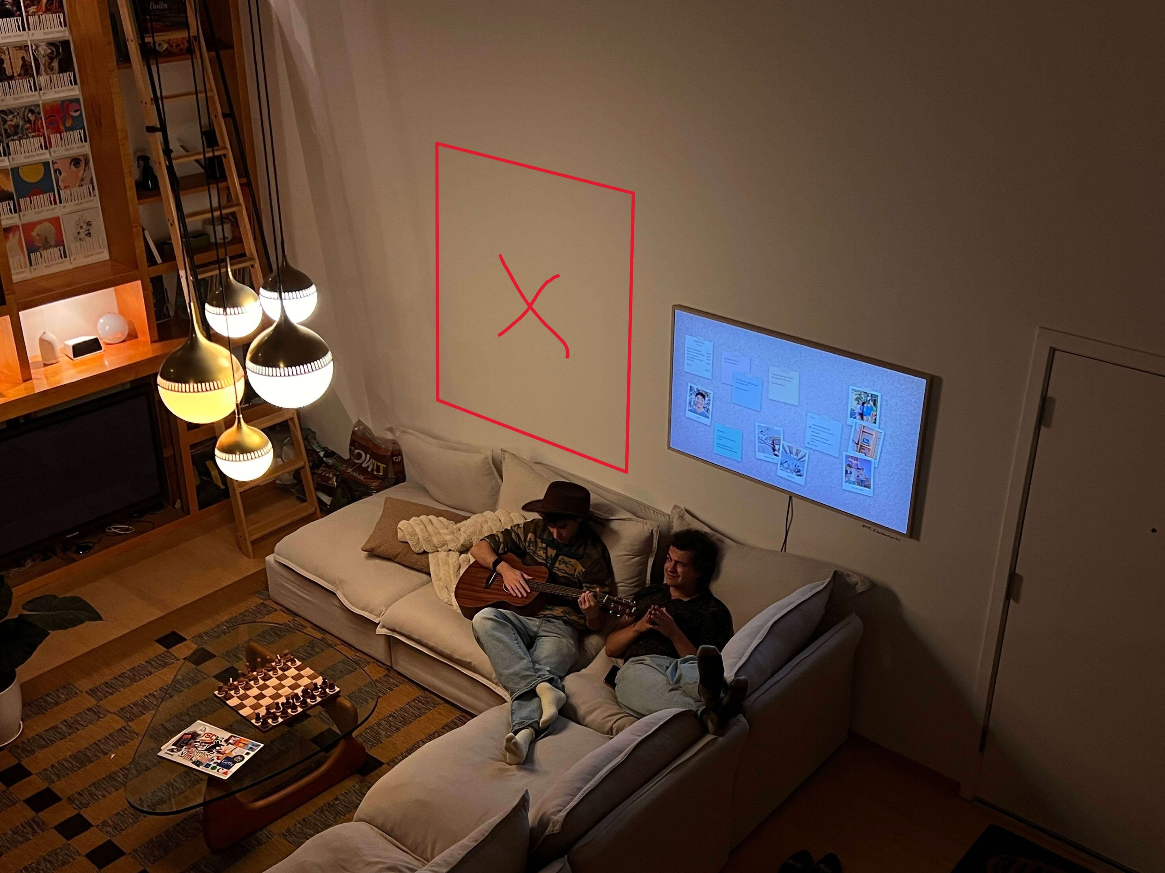
Where I intend to hang the polargraph in my living room.
The machine will be built within a large wooden frame, which mounts flush to the wall via a French cleat system. All electronics and motors will sit behind this frame, between the back of the workplane and the wall, so as to remain hidden out of sight. Both stepper motor axles will protrude through the workplane and will be covered by pieces that also hold endstop switches to enable homing. Counterweights, as well as the center gondola, will be weighted with titanium round-stock, for high density within little area. The gondola itself will be attached to the belts via swivel arms on thin 6806-2RS bearings, to allow for a smooth, constantly upright motion. The gondola is to remain flush against the workplane at all times, so a small servo within it will actuate a pen up and down into/away from the paper. These pens should be easy enough to hotswap, because we want some different colors, of course.
and boom! Easy enough, right? Here it is in all its glory:
… and with the design out of the way, it’s time to make this thing real!
Gondola Assembly
The gondola is the real heart of this beast, so we’ll take on its assembly first. Our gondola here is a modified version of a Makelangelo gondola remix I found on printables.
I printed all the parts on my Bambu Labs P1S in a woodfill PLA. This filament choice has the dual advantage of a) matching the machine aesthetics, and b) being easy to sand in post-processing. And sand I did, to make sure everything fits together smoothly, give all of the parts a good sand before assembly, especially those that mesh/rub against other printed parts.
Assembly is straightforward enough, I’ve included a Fusion 360 embed below to be referenced during the build. We’ll start by press-fitting both of the “arm” pieces onto two 7mm tall 6806-2RS Ball Bearings, before mounting these to the main gondola body, following the orientation shown in the model below.
Then we’ll fix the 3d printed gear to an MG90S Micro Servo, using one of the servo horn screws that came with the servo to fix it in place, before fixing that servo to the main gondola body with a bit of glue and the servo mounting screws. This gear will mesh with the pen holder to move our pen up and down. We’ll hold off on installing this for now until we get the firmware sorted.
We can now move on to balancing the main gondola body with its two counterweights (with some nice little bits of tungsten). The gondola needs sufficient mass to maintain belt tension and surface contact, and proper counterweights reduce the motor load associated with this. We can calculate the weights needed here based on a centered gondola, where each belt supports approximately half the weight:
\[W_{counter} = k \cdot \frac{W_{gondola}}{2}\]
where \(k \approx 0.75\text{-}0.85\) gives good results. I used \(k = 0.78\).
For my setup, the bare gondola weighed 4oz. Adding 3oz of tungsten brought the total to 7oz, with counterweights of 2.75oz each:
\[W_{counter} = 0.78 \cdot \frac{7\text{oz}}{2} \approx 2.75\text{oz}\]
This creates a net downward force:
\[F_{net} = W_{gondola} – 2 \cdot W_{counter} \approx 1.5\text{oz}\]
sufficient for stability without overloading the steppers. Adjust these values based on your drawing area and motor specs (or use mine, probably best to stray a bit heavier here than too light, as we don’t want the timing belts jumping).
I tried to position the tungsten rounds in a roughly uniform pattern within the main gondola and counterweights’ body, ensuring symmetry across all. After the tungsten rounds are installed, you can screw on the top cover of the main gondola (hold off on doing the same with the counterweights for now).
Next, we’ll want to trim our timing belts. To calculate the length you need for each side, we need to account for the maximum belt-to-gondola distance plus sufficient slack for the counterweight system.
The maximum belt length occurs when the gondola reaches the bottom corner furthest from a motor:
\[L_{max} = \sqrt{W^2 + H^2}\]
where \(W\) is the drawing width and \(H\) is the drawing height.
The total belt length per side should be:
\[L_{total} = L_{max} + L_{counter}\]
where \(L_{counter}\) is the counterweight drop distance (typically 200-400mm for an adequate range of motion).
For my 920mm × 1250mm drawing area:
\[L_{max} = \sqrt{920^2 + 1250^2} \approx 1550\text{mm}\]
\[L_{total} = 1550 + 300 \approx 1850\text{mm}\]
I added an extra 150mm as a safety margin, bringing each belt to 2000mm (2m) total length.
Alternatively, you can do this by draping the belts over each stepper (after the frame is built – see later in this article), manually moving the gondola to the furthest corner diagonal from that stepper, and cutting the belt a few cm below the timing pulley (leaving wiggle room to attach the counterweight). Repeat for the other side and attach the counterweights. Less maths, more fun lol.
Then, attach each belt in its corresponding slot in each counterweight before screwing the top of each counterweight secure. To the other end of the belt, attach the 3d printed gondola hooks.
Machine Assembly
With the gondola out of the way, we can continue with the rest of the machine assembly, starting with the machine’s wooden frame. I toyed with scrapping this frame entirely a few times, and was particularly compelled by a suggestion from my roommate to reface the wall with whiteboard wallpaper and scale up the polargraph to cover the entire space. Nonetheless, I progressed with this wooden frame for now (as aesthetically I like it, and it makes electronic containment straightforward), yet you can essentially mount your polargraph gondola to any vertical plane, and alter the marker it uses with very minimal modification.
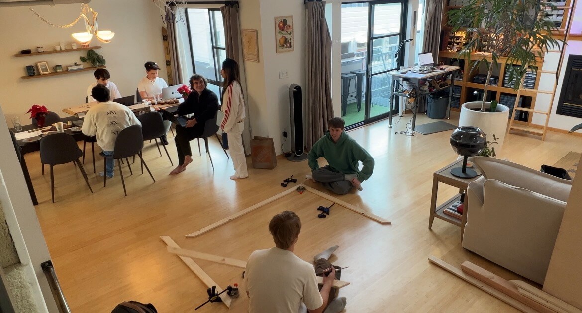
I spent the better half of a morning on a plywood run with my buddy Aidan, and hauling all the lumber needed for the machine up to my walk-up unit:
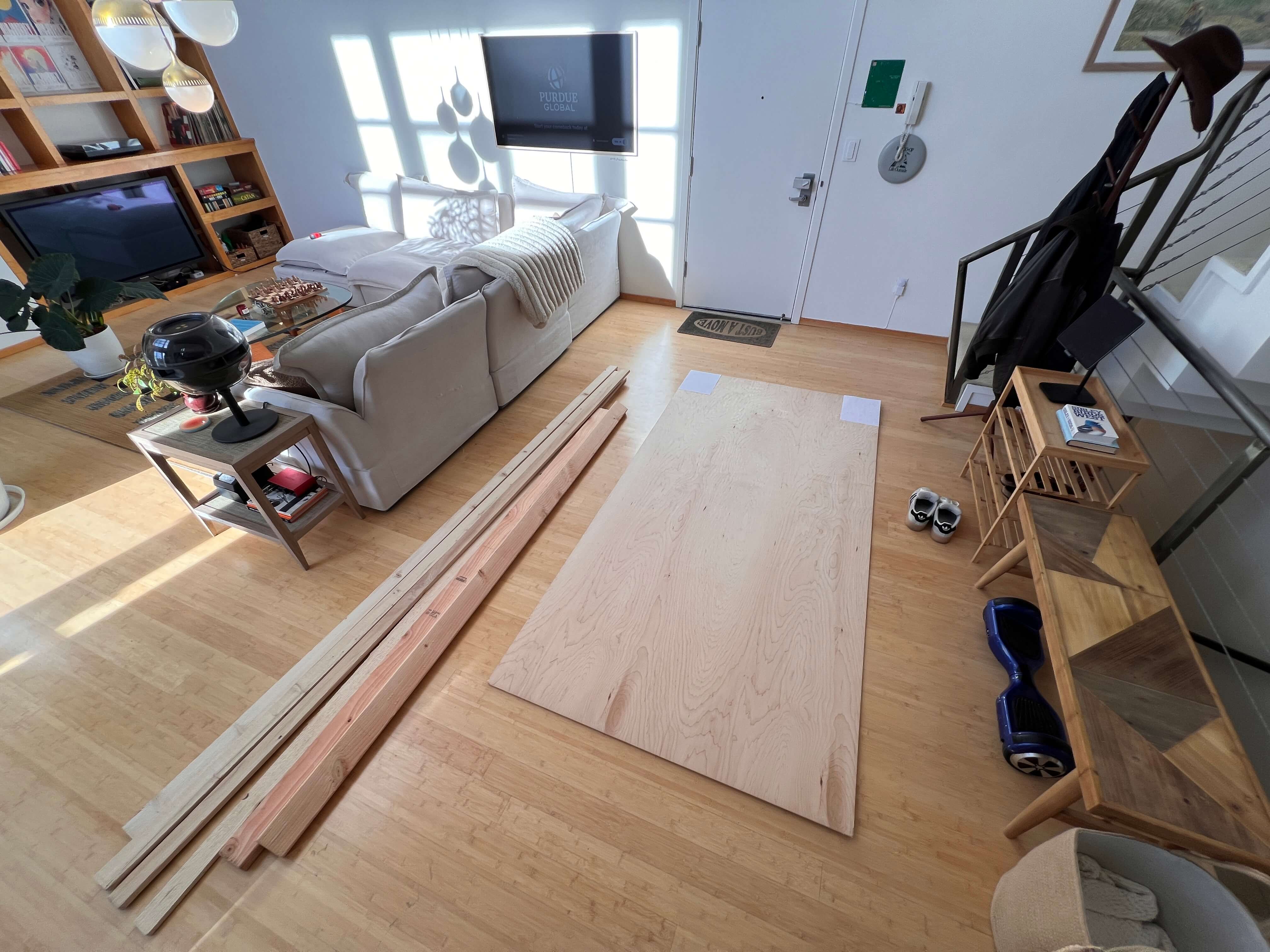
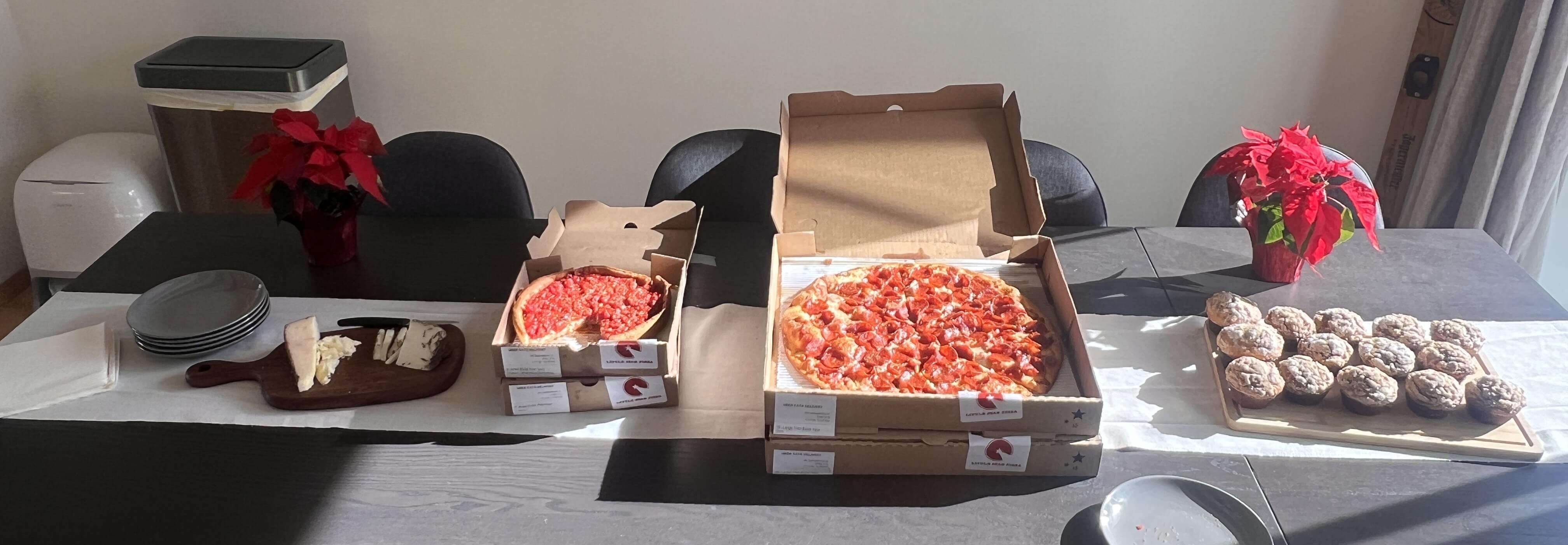
… which was certainly a good workout. I figured that processing all this lumber in my apartment would take quite a while solo, and I was on a bit of a time crunch finishing this build, so I ordered a bunch of pizzas and had a few friends over to help out!
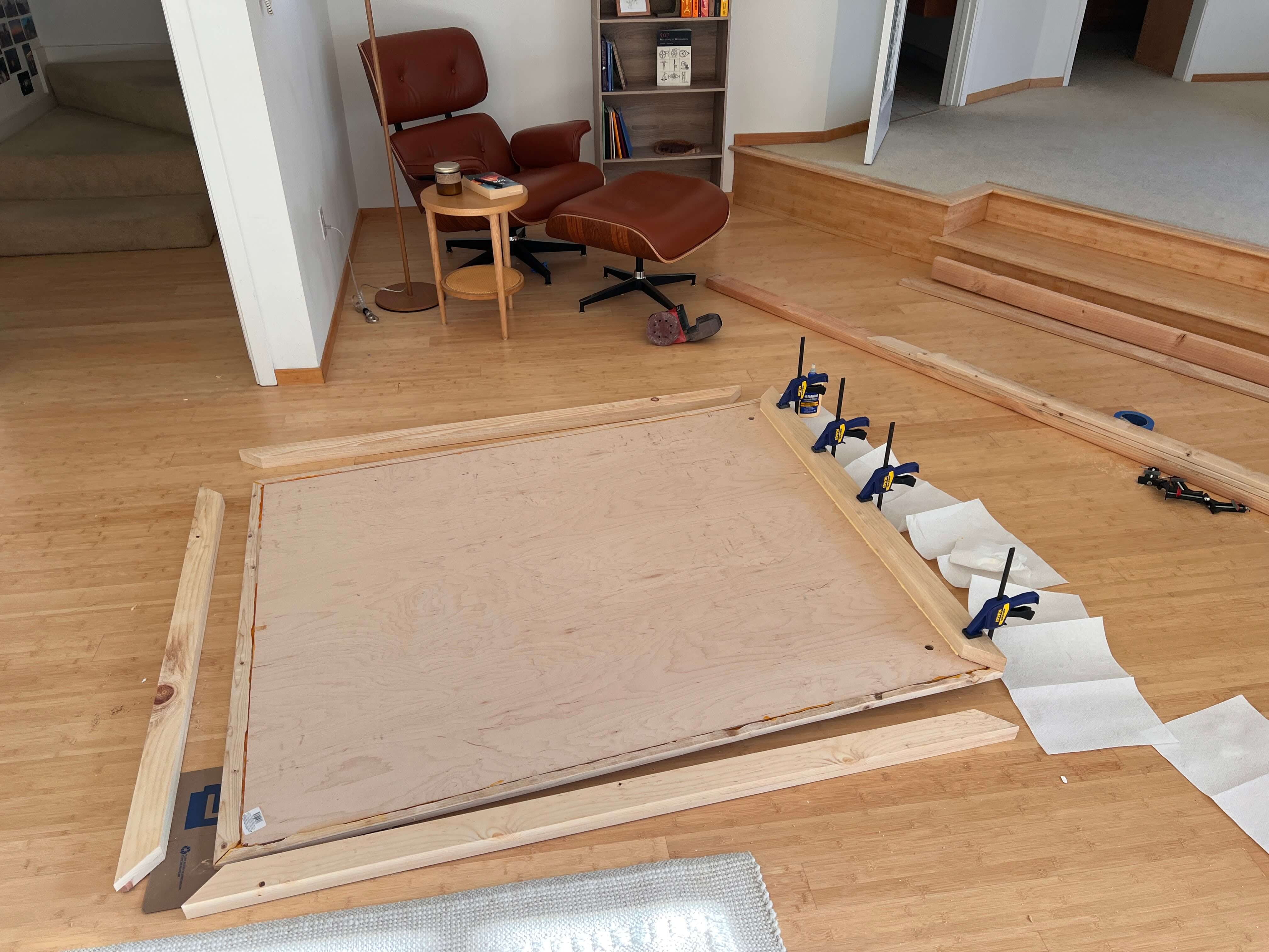
We hacked together this frame with some 1×3” boards and a full (4×8’) sheet of 1/4” maple ply. I started by cutting the 4×8’ plywood sheet down to 48×60” to match the specs of the Fusion file, and immediately realized that all the dimensions I chose for the wooden frame of this machine were somewhat arbitrary and kind of a pain to process actual stock wood into. I only say this in hindsight, and frankly recommend reconsidering your machine dimensions if you’re building this for yourself.
I wanted to frame this sheet of plywood with some miter-style border. I tried pulling this stunt off with a Japanese handsaw and failed my angles miserably, so I wound up buying a cheap miter saw to finish the job. My buddy Graham and I took out a 1/4” deep dado on the back inside edge of all four plywood boards that make up this miter-frame, so that our 48×60” plywood backing can sit flush within it.
Then I cut two more sets of identical miter frame boards to stack to continue our wooden frame behind the plywood sheet. This is where we’ll be positioning all of the machine’s electronics to remain out of view while mounted against the wall.
And while I took the leap and bought a few proper tools for this build, this was built on the floor of my apartment after all (I still need to find a good woodshop in San Francisco – ping me if you know a place!), and as such, I had no lack of weird gaps to woodfill.
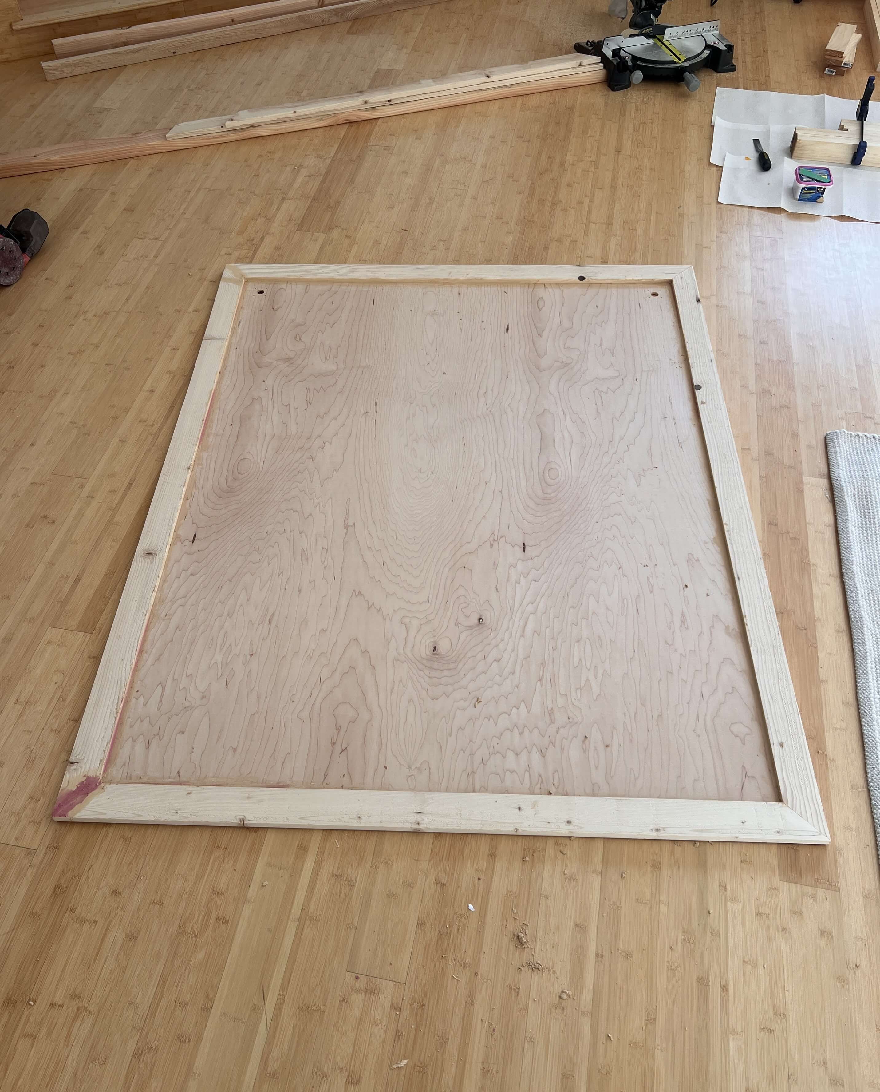
I made some printable jigs based on my Fusion file to help place and mount the steppers on the machine’s plywood backing. I just mounted these in the top corners of the wooden frame with some blue tape and drilled the mounting holes out.
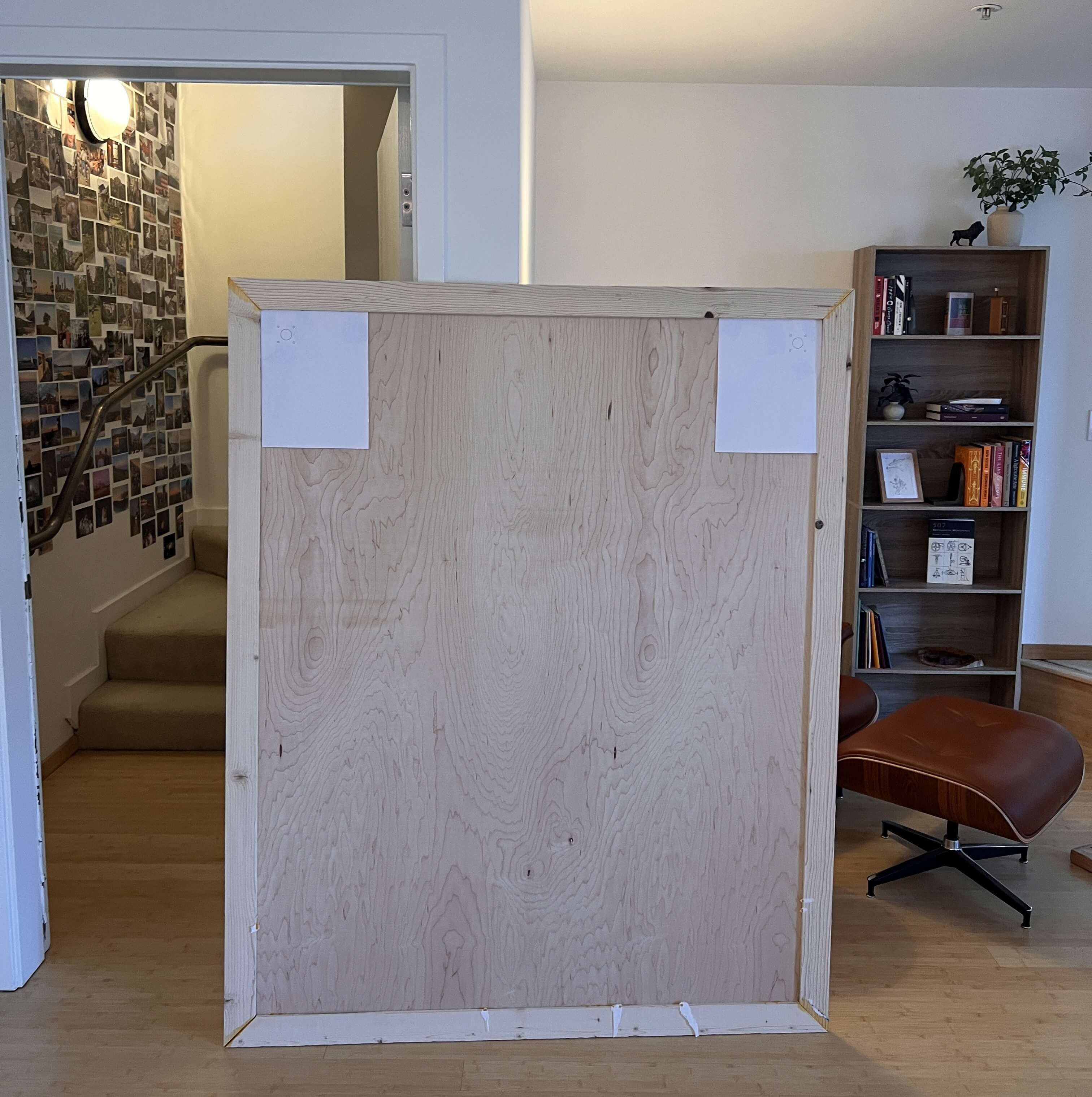
Then came sanding, more wood filling, and more sanding to wrap up the bulk of this project’s woodworking before moving onto the electronics!
Wiring
The electronics behind a pen plotter are really straightforward: 2 steppers, a single servo, two endstops, not much else. I based GPenT’s electronic design around a cloned Arduino Mega 2560 and a RAMPS 1.4 shield that I had lying around, but you could build this out with really any old mainboard you have laying around with minimal modification. A complete interactive diagram of GPenT’s electronics can be found below.
To start, mount the RAMPS 1.4 shield atop the Arduino Mega, and then stack on the two A4988 stepper drivers, on the X and Y driver slots respectively (note that these drivers aren’t shown in the diagram below for legibility purposes, but I included one in a higher slot for polarity reference). Polarity matters here! Be sure you match the orientation of the single driver shown in the diagram below with both of your two drivers.
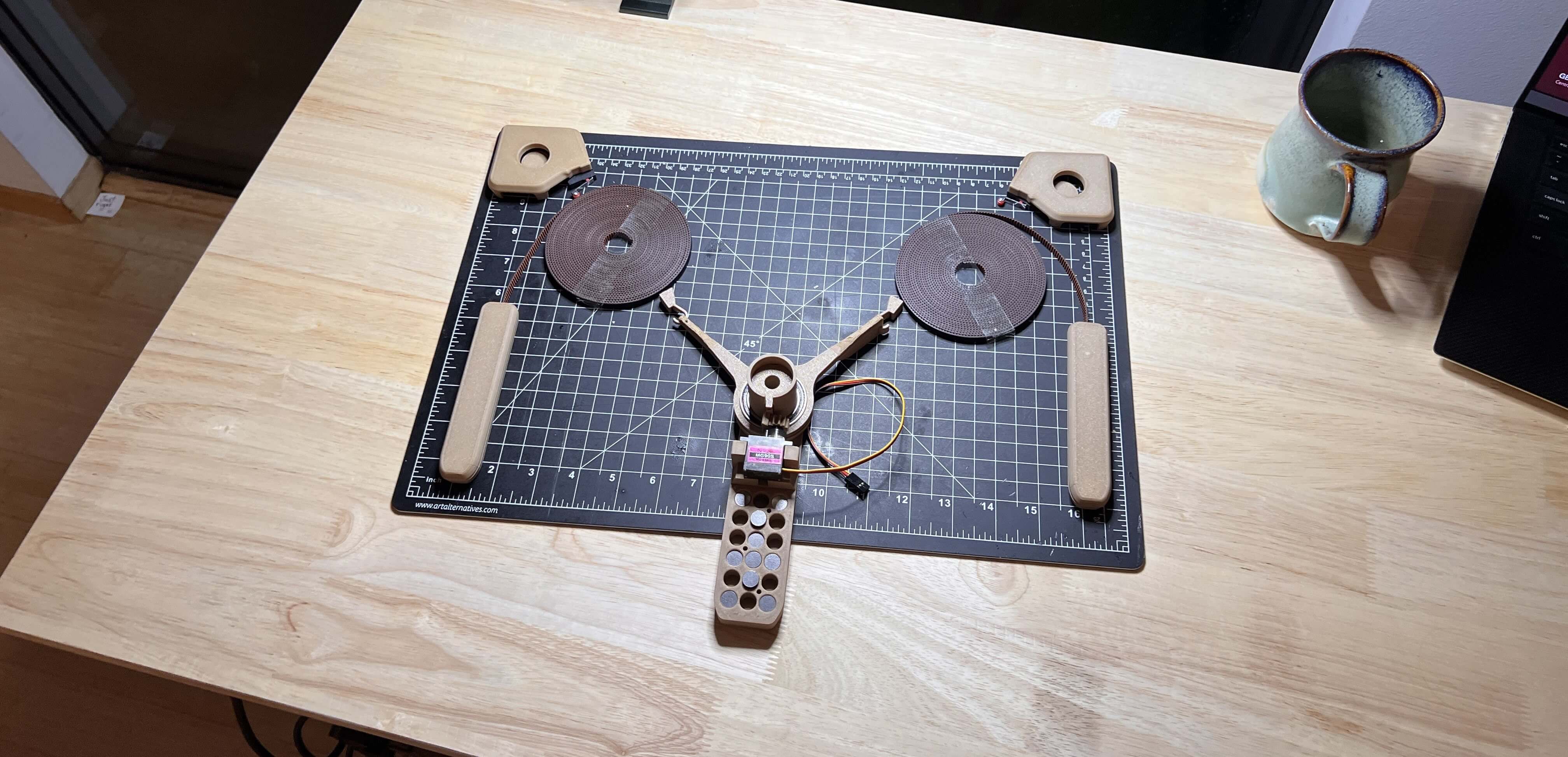
Then I attached a timing pulley to each of our two steppers …
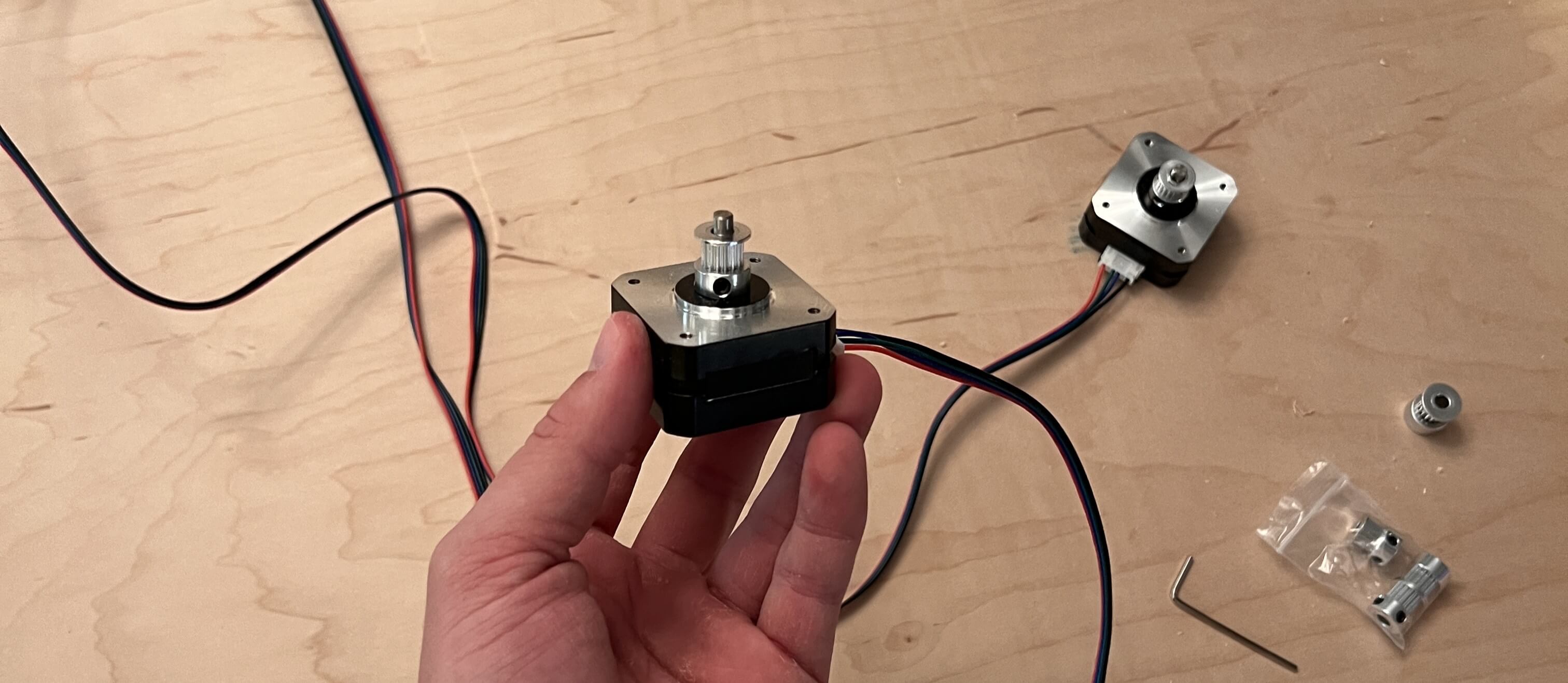
and wired both motors to the corresponding X and Y motor headers on the RAMPS shield, before mounting both steppers to our wooden backing.
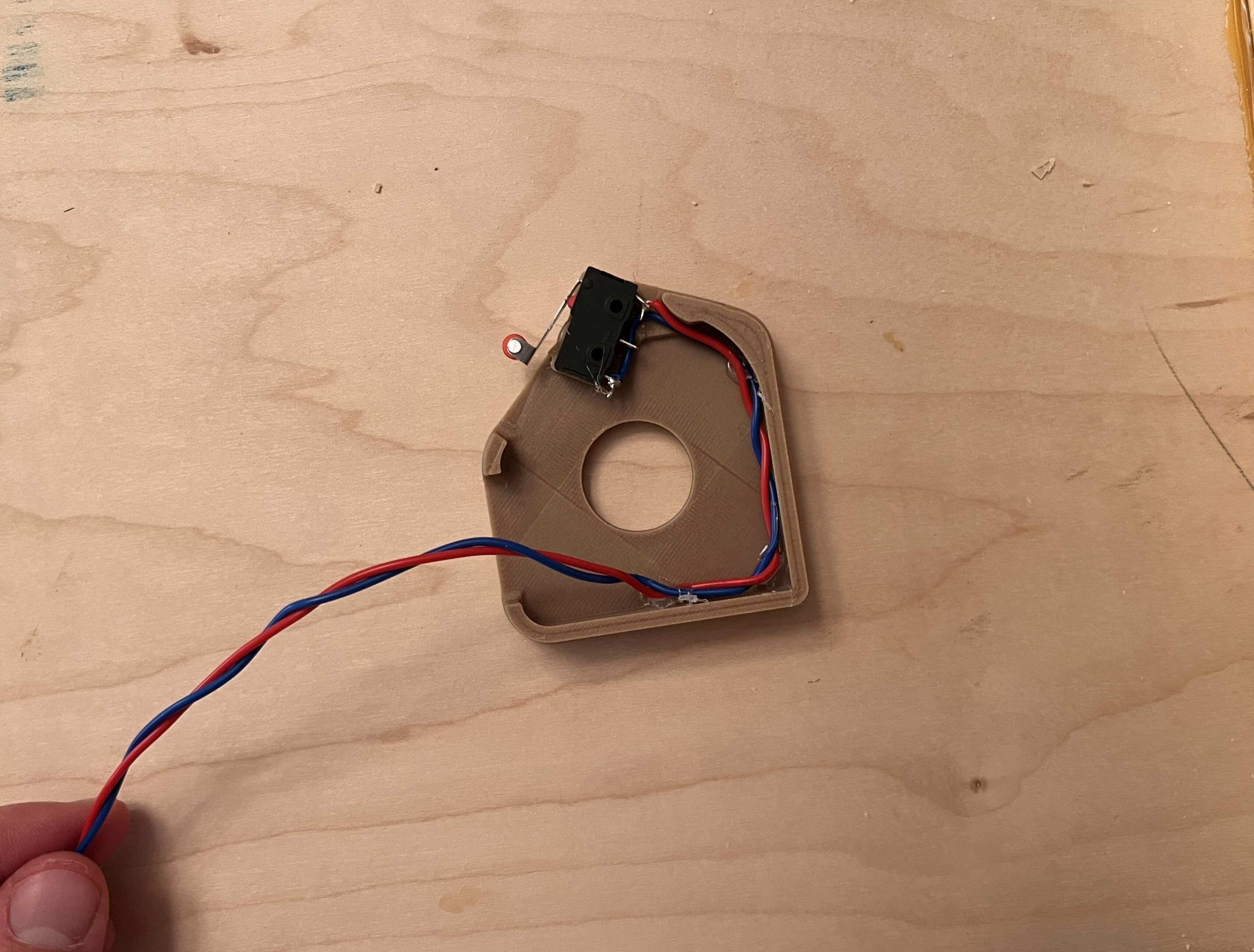
Next up, the endstops. I wired our two endstops on X-MIN and Y-MIN on the RAMPS shield and used a bit of hot glue to mount them in place on our motor cover brackets. See both these mounted switches, as well as our mounted steppers below.
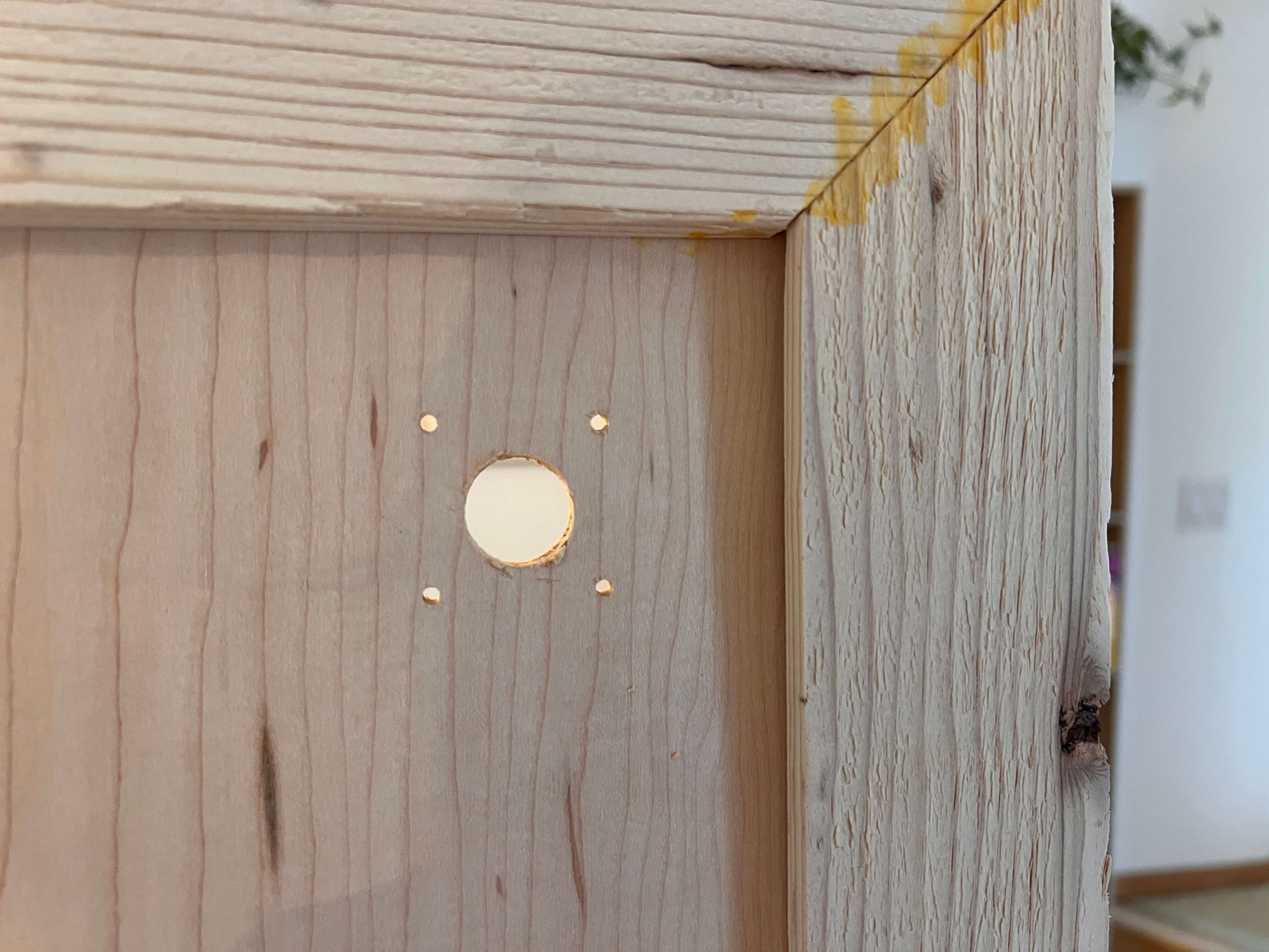
Now, these motor cover brackets need to sit on the front side of our machine, so that we can pass the cables for the switch and servo through to the front, I drilled a small hole close to the mounted stepper …
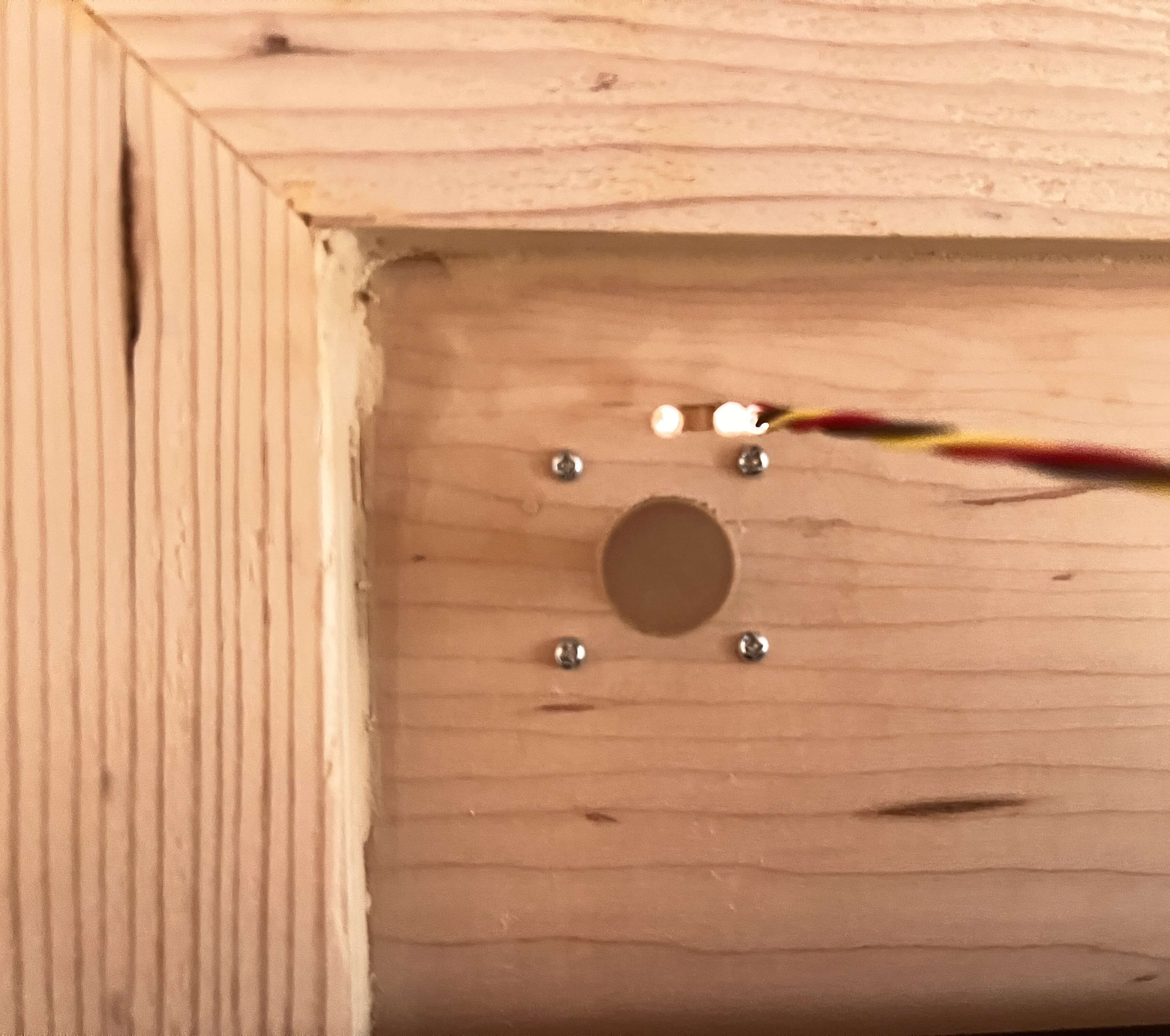
before passing the cables through those holes and hot gluing the motor cover in place. The gondola servo is wired to SERVO0 on the RAMPS shield, and its cables are passed from the front to the back alongside the endstop cables under the right motor cover. (You’ll need a long length of wire to do this)
To position the motor covers properly, I mounted endcaps atop both stepper motor axles (see mounting on the right below). On the back of the machine, I mounted our Arduino + RAMPS shield, our Raspberry PI, the PSU, and the buck boost converter with a bit of hot glue, before routing all of the wires with, you guessed it, even more hot glue.
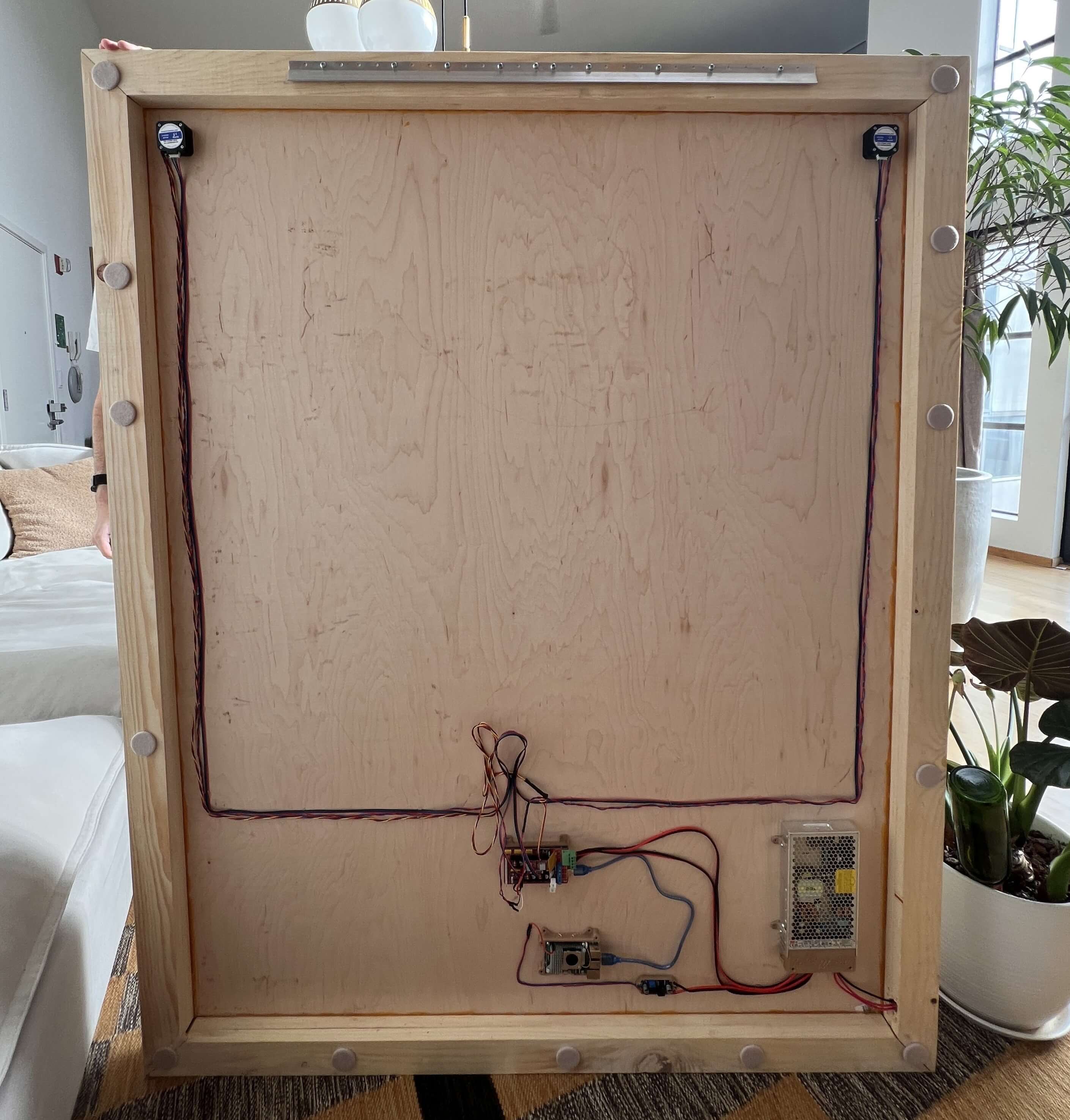
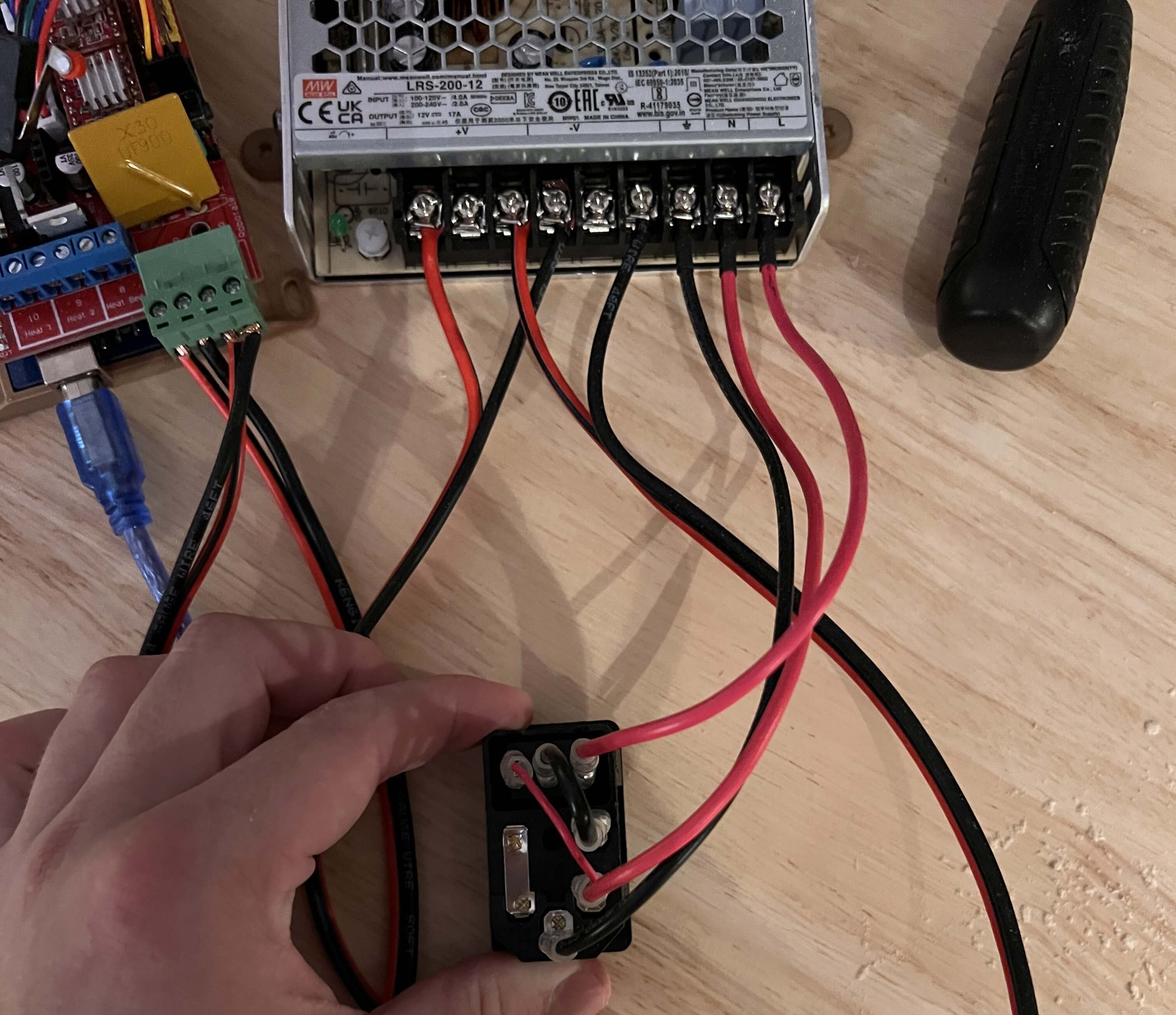
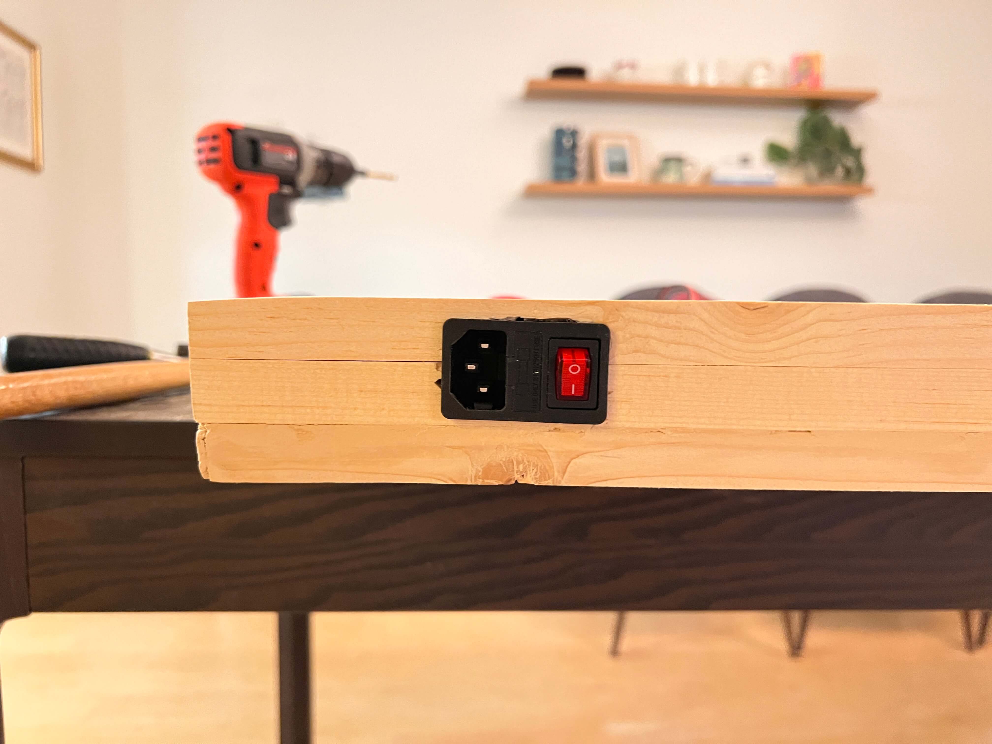
The power for the whole machine is passed through a C14 rocker socket, which I have inlaid in the side of GPenT’s wooden frame (with some drilled holes and some chiseling). This is wired directly to our PSU, which is attached to the power sockets on the RAMPS shield, as well as to a buck boost converter where it’s stepped down to 5V and routed to our Raspberry Pi. Finally, the Raspberry Pi is connected to the Arduino Mega via a USB cable.
Wiring done! Onto firmware.
Firmware
The firmware behind pen plotters is about as easy as it gets (given that easy enough wiring from above). I’m using Marlin as a base, and starting with the same config as the Makelangelo firmware for compatibility out of the box with the Makelangelo software, more on that later.
To start I modified the stock Marlin firmware to target an Arduino Mega 2560 with a RAMPS 1.4 shield to match our machine, set our two NEMA 17 stepper motors on the X and Y driver slots (left and right belts respectively), set our pen-lifting servo on SERVO0 (pin 11), and the two endstops on X-MIN and Y-MIN. All extra pizzazz like LCD screens, SD cards, heated beds, etc, etc I disabled to streamline the builds. See these configuration changes for yourself in src/local_config.h and the PlatformIO build environment in platformio.ini.
To build and upload this firmware for yourself, you’ll need to install the PlatformIO Core and clone my firmware repository.
Then connect your Arduino Mega to your computer via USB. When connecting any machines to your computer, be wary that the machine’s PSU is on and powered in before connecting the machine via USB. If you don’t do this, you run this risk of powering your steppers through your mainboard/laptop USB power, frying your mainboard and USB port in the process!
Note the COM port of your Arduino (e.g., COM3 on Windows, /dev/ttyUSB0 on Linux). Then open a terminal in the Makelangelo-firmware directory and run:
Replace YOUR_COM_PORT with your actual port. The firmware will compile and flash automatically.
Then, with the Arduino still connected, run the included center servo script to align the servo to a proper 90°, then disconnect, shut off your machine. Manually move your servo 1/4th of a full rotation, and then push the pen mount into place, meshing with the servo gear and rotating it back to approx 90°.
You may now power your system back on, reconnect to the Arduino, and run the test script with:
This will verify your servo moves between pen-up (~90°) and pen-down (~40°) positions, and that both stepper motors respond to movement commands in both directions. If everything moves as expected here, congrats! You’re done with the physical build 🙂
If you’re building a machine of your own, you can set/refine your dimensions easily with this little calibrate.py script I wrote (this is also in the /settings tab on plotter dot local, more on that UI later). I found even while building my machine to scale set in CAD, my actual machine dimensions were ever so slightly off, which can have a notable impact on the polar grid. Easy fix, properly calibrate your machine!
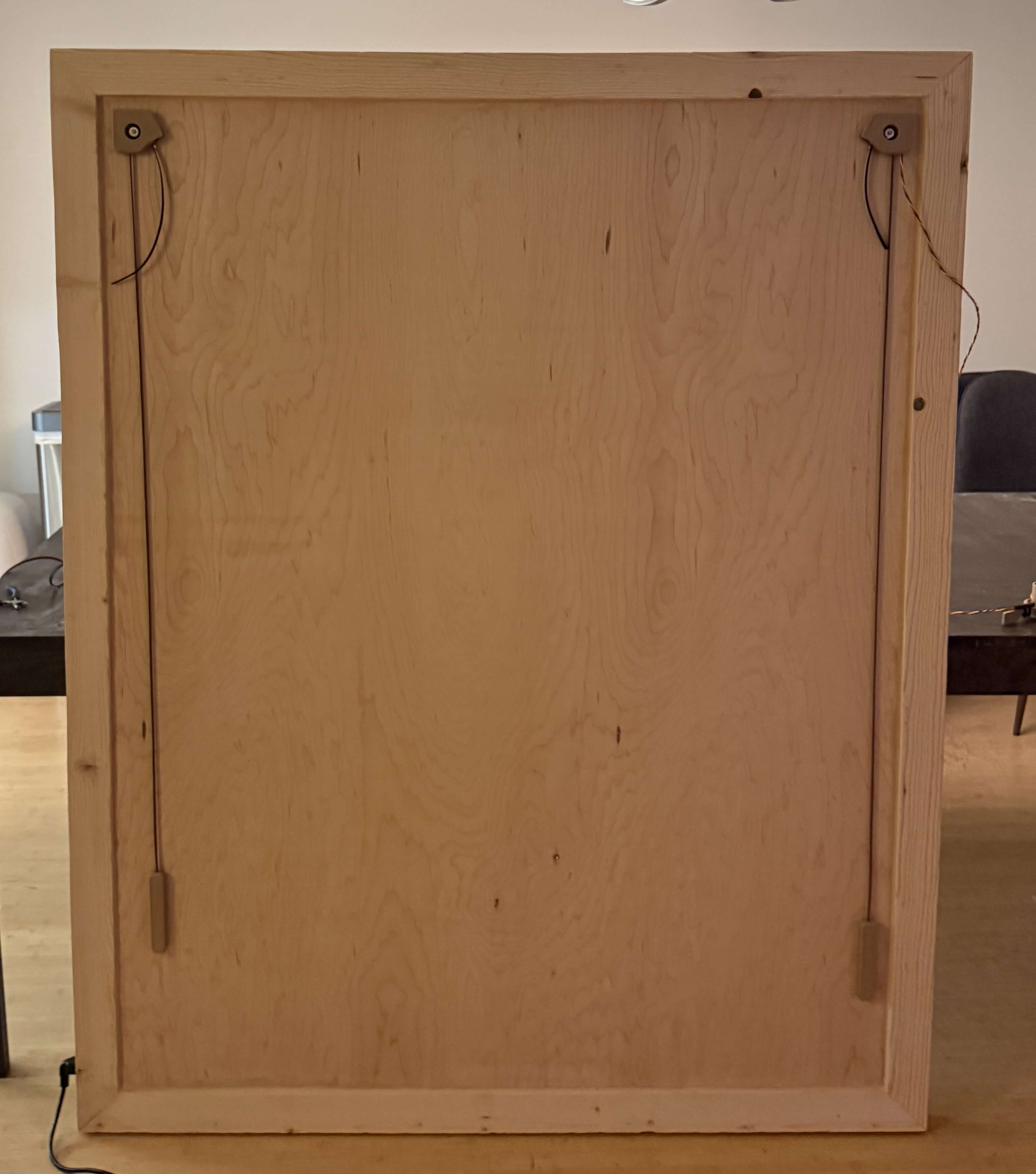
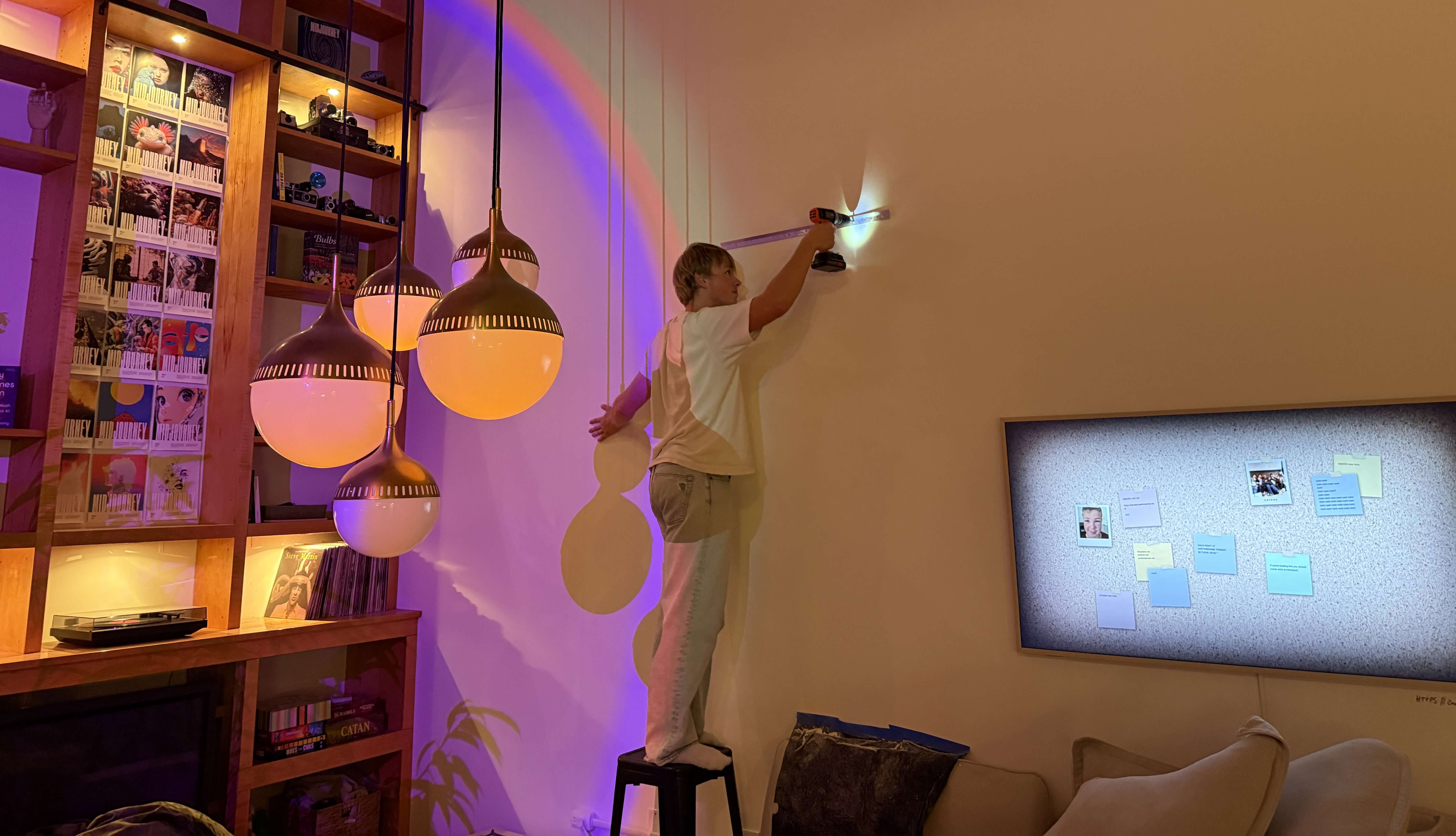
To mount the whole thing to the wall, I used this cheap, 30 in. 300 lb. french cleat from Home Depot. I screwed the top cleat to the top board of GPenT’s wooden frame, and then mounted the bottom cleat to my wall. Pardon my lack of ladder, lol.
… and here’s the mounted machine, in all its glory!
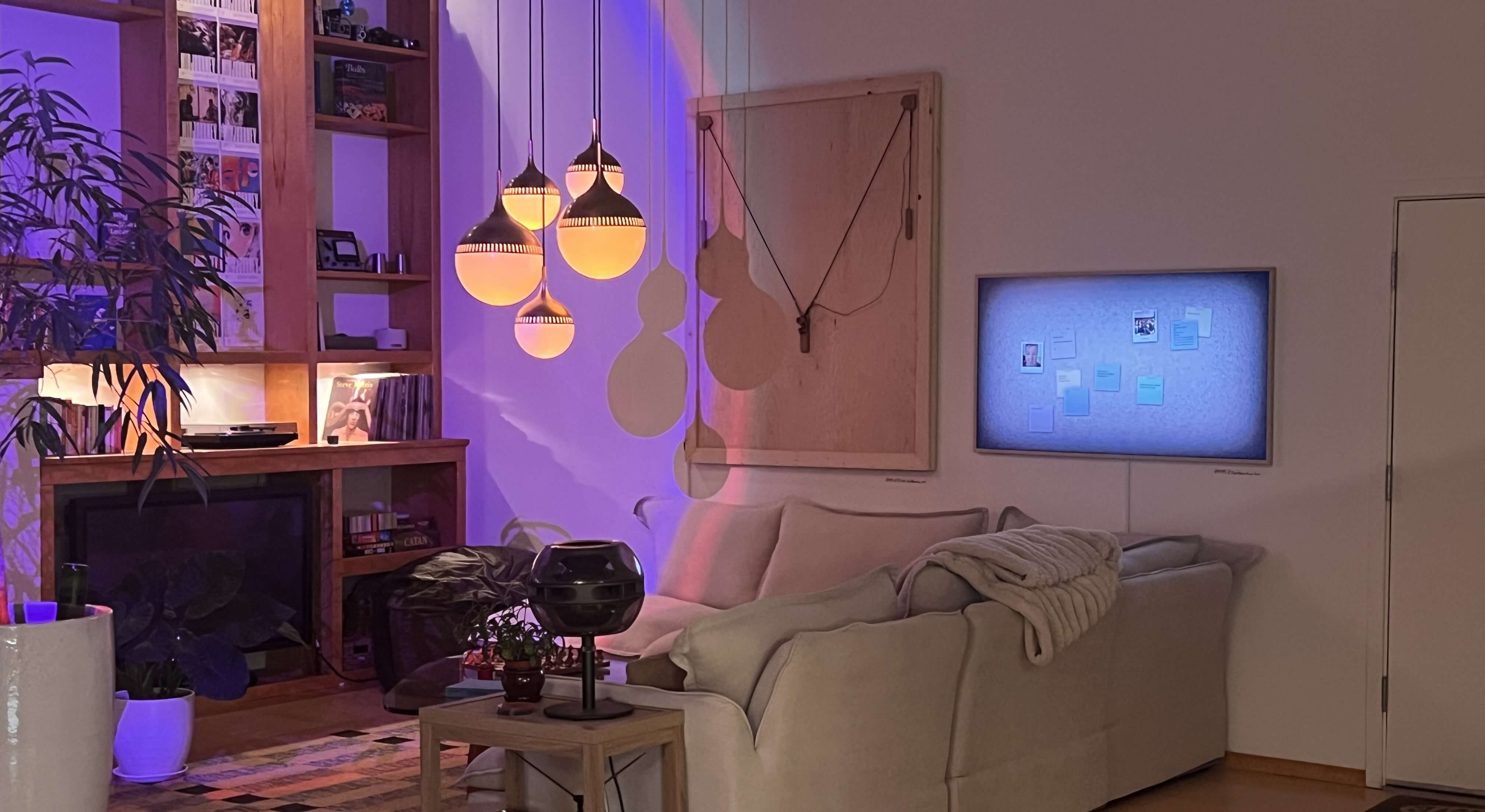
I used some felt pads on the back corners of the machine to be sure it didn’t mark up my wall. I found that stacking a few additional felt pads on the bottom corners of the machine helped ensure proper pen pressure by setting the entire frame slightly angled backward.
BOM
The full project repo is at github.com/Twarner491/polargraph. Here’s all you need:
| Qty | Description | Price | Link | Notes |
|---|---|---|---|---|
| 1 | Raspberry Pi 5 | $89.94 | Link | 8GB |
| 1 | Raspberry Pi 5 Active Cooler | $9.90 | Link | |
| 1 | Micro SD Card | $16.68 | Link | ≥32GB |
| 1 | RAMPS 1.4 Shield | $9.39 | Link | |
| 2 | A4988 Stepper Drivers | $9.98 | Link | |
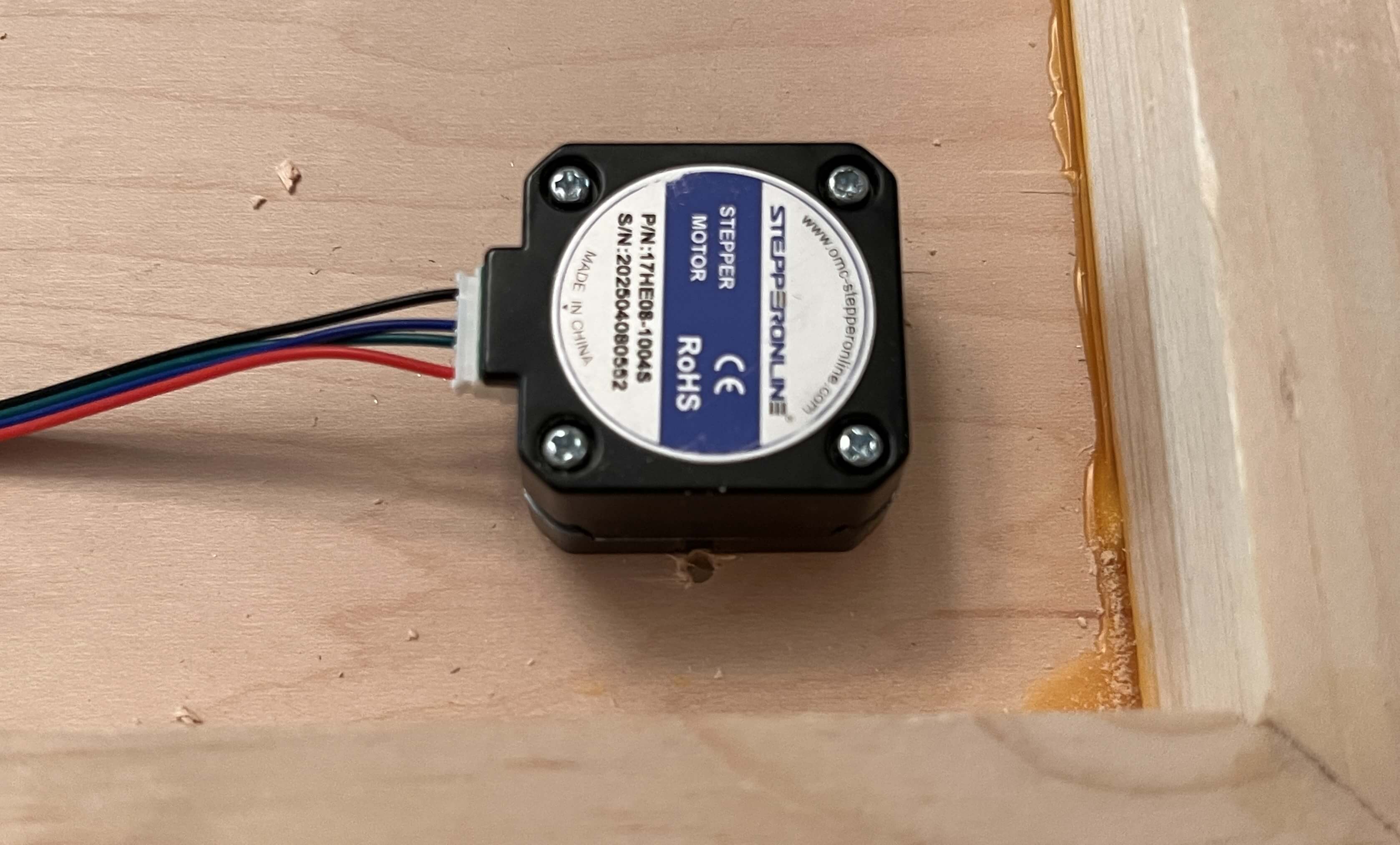
| 2 | Nema 17 Pancake Stepper | $21.00 | Link | 42mm x 23mm |
| 1 | MG90S Micro Servo | $9.99 | Link | 9G |
| 2 | Stepper Motor Cables | $10.99 | Link | 2M length |
| 2 | GT2 Timing Belt | $19.98 | Link | 6mm width, 5M length |
| 2 | GT2 Timing Belt Pulley | $6.99 | Link | 16 Teeth, 5mm bore |
| 2 | 6806-2RS Ball Bearings | $30.00 | Link | 30mm x 42mm x 7mm |
| 1 | 12V Power Supply | $35.00 | Link | |
| 1 | DC/DC Buck Boost | $9.99 | Link | |
| 1 | C14 AC Inlet | $9.04 | Link | |
| 1 | AC Power Cord | $9.39 | Link | Down angle |
| – | 14 Gauge Wire | $13.99 | Link | A couple feet |
| 2 | Limit Switch | $5.99 | Link | |
| 3 | Tungsten Weights | $89.97 | Link | |
| 1 | 1/4” Maple Plywood | $37.71 | Link | 4’x8’ sheet |
| 4 | 1”x3” Spruce Pine Boards | $27.92 | Link | 8’ length |
| 1 | Wood PLA | $25.99 | Link | 1.75mm, 1 spool |
| 1 | A0 Paper Roll | $29.86 | Link | 36” x 1200” |
| 1 | SAKURA Pigma Micron 05 Pens | $20.97 | Link | Multicolor pack |
| 1 | French Cleat | $31.00 | Link | 30 in. 300 lbs. |
| 1 | Felt Pads | $9.97 | Link | Assorted Pack |
| – | M2 and M3 Hardware | – | – | Misc nuts and bolts |
| – | Jumper Wires | – | – | Misc |
Total: ~$595.82
Plotter [dot] Local
I hinted earlier at the real reason we’re sticking around this Makelangelo firmware so much: the Makelangelo software. This is great, it bakes a full CNC control UI with a bunch of fun turtle scripts to generate little patterns for the plotter to draw. I figure this is a great base to build on, especially all these little turtle scripts, but I like all of my projects to be entirely standalone, meaning we’re gonna need a web server and we’ve got some work ahead of us.
…
Just kidding, I wrote it already! I’m hosting a publicly accessible version of the site at plotter.onethreenine.net, which you can use to create and export plotter compatible gcode/SVG files for yourself! Try it out below:
If you’ve been following along and building a machine of your own, we’ll want to get this UI up and running on your machine’s Raspberry Pi. To start, get a fresh copy of Raspberry Pi OS Lite (64-bit) onto an SD card and update the WiFi credentials. Then let’s SSH in and get to work:
# SSH into your Pi
ssh [email protected]  # Default password is usually 'raspberry'

# Update system
sudo apt update && sudo apt upgrade -y
I like custom hostnames, as I’ve got way too many RPI’s on my network. We’ll set the hostname to ‘plotter’ – this allows users to navigate to plotter.local to access the web interface.
# Set hostname
sudo hostnamectl set-hostname plotter

# Update hosts file
sudo nano /etc/hosts

# Change the line: 127.0.1.1 raspberrypi
# To: 127.0.1.1 plotter
# Save: Ctrl+O, Enter, Ctrl+X

# Reboot to apply
sudo reboot
After reboot, reconnect with:
Then install dependencies:
# Install system packages
sudo apt install -y python3-pip python3-venv avahi-daemon git

# Enable and start mDNS service
sudo systemctl enable avahi-daemon
sudo systemctl start avahi-daemon
Now we’ll clone the project repository. The full source lives at github.com/Twarner491/polargraph:
git clone https://github.com/Twarner491/polargraph.git ~/polargraph
cd ~/polargraph

# Create virtual environment
python3 -m venv venv
source venv/bin/activate

# Install Python dependencies
pip install -r requirements.txt
To get our RPI app up and running with the plotter, we need to set USB permissions for the serial connection.
sudo cp system-config/99-polargraph.rules /etc/udev/rules.d/
sudo udevadm control --reload-rules
sudo udevadm trigger

# Add user to dialout group for serial access
sudo usermod -a -G dialout pi

# Reboot for permissions to take effect
sudo reboot
As a final step, we’ll set up this Flask server to auto-run upon boot.
sudo cp ~/polargraph/system-config/polargraph.service /etc/systemd/system/
sudo systemctl daemon-reload
sudo systemctl enable --now polargraph.service

# Check status
sudo systemctl status polargraph.service

# Test reboot
sudo reboot
After reboot, http://plotter.local should be live automatically!
If you saw my Quote Receipt project, you’ll know I like to route all of my locally hosted projects through a Home Assistant Yellow in my apartment, so they’re accessible from anywhere in the world. This is totally optional, but if you happen to have a Home Assistant setup of your own, you can port plotter.local to a public-facing domain of your choosing:
Home Assistant Integration (Optional)
Our setup here is about the same as our Quote Receipt setup: a webhook automation in Home Assistant receives commands from the frontend, publishes them to an MQTT topic, and an MQTT subscriber script on the Pi listens for messages and triggers the plotter. This allows the frontend to be hosted publicly (via plotter.onethreenine.net) while the plotter itself remains on the local network, bridged through Home Assistant.
Home Assistant Automation
Add to automations.yaml:
alias: "Polargraph Command"
trigger:
  - platform: webhook
    webhook_id: polargraph_command
    allowed_methods: [POST]
    local_only: false
action:
  - service: mqtt.publish
    data:
      topic: "home/polargraph/command"
      payload_template: "{{ trigger.json | tojson }}"
Enable CORS
Add to configuration.yaml:
Pi MQTT Setup
Edit src/mqtt_subscriber.py with your MQTT broker IP:
Then enable the MQTT service:
sudo cp system-config/polargraph-mqtt.service /etc/systemd/system/
sudo systemctl daemon-reload
sudo systemctl enable --now polargraph-mqtt.service
Frontend Configuration
Edit build_static.py and set your webhook URL:
Sonakinatography
I’ve always really enjoyed pen plotter art, or frankly, any thin line drawings. One of my favorite twitter accounts is @adamfuhrer, who fills my timeline with a ton of aesthetic plots/sketches. One of his recent tweets really caught my eye, highlighting the works of Channa Horwitz:
Horwitz invented a complete visual notation system constrained to 1/8” graph paper several decades ago (1968), which she coined: Sonakinatography. All of her works were done entirely by hand, which is absolutely bonkers, as they’re so meticulous they look computer generated. While I’m not quite confident I hold a steady enough hand to practice these plots true to her method, I now happen to own a wonderful, wall-mounted polargraph!
In sonakinatography, there are 8 entities, each given a corresponding number. Each entity occupies a certain number of grid squares on 1/8” graph paper, corresponding to the number of “beats” present within that entity. In this sense, the duration of an entity (or beat count) is equivalent to its visual magnitude. While you can use this method to visualize a whole bunch of data and a whole bunch of interesting fashions, I’m going to constrain our entity type for now into poems and phrases (as beat count feels particularly obvious here). We’ll map each word in a poem/phrase to an entity (1-8) based on its syllable count.
\[\text{word} \xrightarrow{\text{syllable count}} \text{entity } n \in \{1,2,3,4,5,6,7,8\}\]
A one-syllable word becomes entity #1 (and occupies 1 beat), a two-syllable word becomes entity #2 (and occupies 2 beats), and so on. The poem/phrase reads left to right across the 8-column grid, with each word placed sequentially. The vertical axis here shows temporal progression through the poem/phrase, and the resulting pattern visualizes the poem/phrase’s rhythmic structure as a landscape of rising and falling durations.
Try some of this poem/phrase constrained sonakinatography out for yourself:
Select an example or enter text above
* Visualization rotated 90° from Horwitz’s vertical format for space efficiency
dcode
All these turtle scripts and sonakinatography algorithms are cool, but this is the Generative Pen-trained Transformer after all! I certainly can’t call this project complete without some ML shenanigans.
I’ve had this network I’ve been wanting to train for a while, and finally found a good excuse in this project: dcode, text to gcode diffusion. I took a simple enough approach here: take Stable Diffusion’s visual understanding and then redirect it. Instead of decoding latents into pixels via Stable Diffusion’s VAE, I’m attempting to decode them to gcode via a transformer. The whole end-to-end process flushes out to Text prompt → CLIP → UNet diffusion → latent → gcode decoder → plotter-ready commands.
I started by building out a dataset of image-gcode pairs by running art images from a dataset of images of pieces of art I found on Kaggle through five vectorization algorithms, each captioned with BLIP.
My first training attempt, I trained this decoder on whatever latents the diffusion process produced, which in hindsight was a bit silly, as these latents are noisy by design, and as such, there was no stable signal for the decoder to learn from and the model collapsed. I pivoted to using VAE encoded image latents, which deterministically map each image to some fixed latent, giving me the consistency I needed for my decoder training targets.
This seemingly worked structurally, and my next attempt at the network learned gcode syntax, but output the same coordinate over and over again. My best guess was that this decoder was too small, so the final piece of this puzzle was scale … I wish. I scaled up my network to a 200M parameter transformer decoder with a CNN based latent projector, and ran 20 epochs across 8x H100s and saw a loss drop from 3.7 to 0.17! However, semantic understanding remains incredibly limited. The model learned gcode structure but not meaningful content – here’s its attempt at “a sketch of a horse” for instance, lol.


The fundamental challenge here is that the latent space learned by Stable Diffusion’s VAE is optimized, of course, for pixel reconstruction, not gcode path planning. A true dcode, text-to-gcode model likely needs to be trained end-to-end with gcode as the target modality. I would really, really like to get one of these working sometime soon, but for now, my compute budget is depleted (those H100’s are expensive!)
Nonetheless, the network in its current state is available on HuggingFace as well as baked into the plotter [dot] local interface so you can try it out for yourself!
GPenT
The final generator in plotter [dot] local brings us back to the origins of this project: it’s time to implement the Generated Pen-trained Transformer itself. I figure it’s best to return back to my initial intuition: “to use an LLM to generate a string of numbers, to generate SVG blobs, to feed to a pen plotter, and to call the whole thing the Generative Pen-trained Transformer”. Except now there’s no need to limit ourselves to SVG blobs, we have a bunch of generators to work with!
I built out a super simple Gemini instance to handle this. I pass in some keyword (a “whisper” of inspiration if you will) into the Gemini API, as well as a randomized list of generators and color options in a structured prompt that gives Gemini control over the pen plotter. The model then responds with JSON commands specifying which generators to run, with what parameters and transformations, and in which colors. All of this is passed into plotter [dot] local, and is plotted in the workplane.
You control a pen plotter. Canvas: 841mm x 1189mm.

Whispers: "ocean waves"

GENERATORS:
  9: Flow Field - options: lines (50-1000), length (10-200), scale (0.001-0.1)
  1: Spiral - options: turns (1-50), spacing (1-20)
  22: Kaleidoscope - options: symmetry (4-16), pattern (curves/lines/spirals/petals/geometric), complexity (5-20)
  ... (25 generators, order randomized)

COLORS:
  3: Blue
  2: Black
  4: Green
  ... (9 colors, order randomized)

TRANSFORMS: scale (10-300%), rotation (0-360), offset_x (-400 to 400mm), offset_y (-550 to 550mm)

Respond with JSON array. Say FINISHED when done.
[
  {"thought": "...", "generator": , "options": {}, "color": , "scale": 100, "rotation": 0, "offset_x": 0, "offset_y": 0},
  ...
]
I’m shuffling generator and color orderings for each request to prevent Gemini from favoring early-listed options. My initial tests show this is quite effective at getting more varied results. See the fully Gemini worker source at workers/gpent-worker.js – this is about as minimal as it gets. It was my goal to give Gemini as ‘unbiased’ a prompt as possible, yet I bet you could get some really interesting results with a bit more time spent prompting.
Gallery
I am so stoked with how this project came together, and it feels really good to have dusted off an old project from the shelf and to have seen it through. My apartment walls are a little less bare now. I’ve captured some of my favorite plots, check them out:
Enter your email to receive the occasional update.